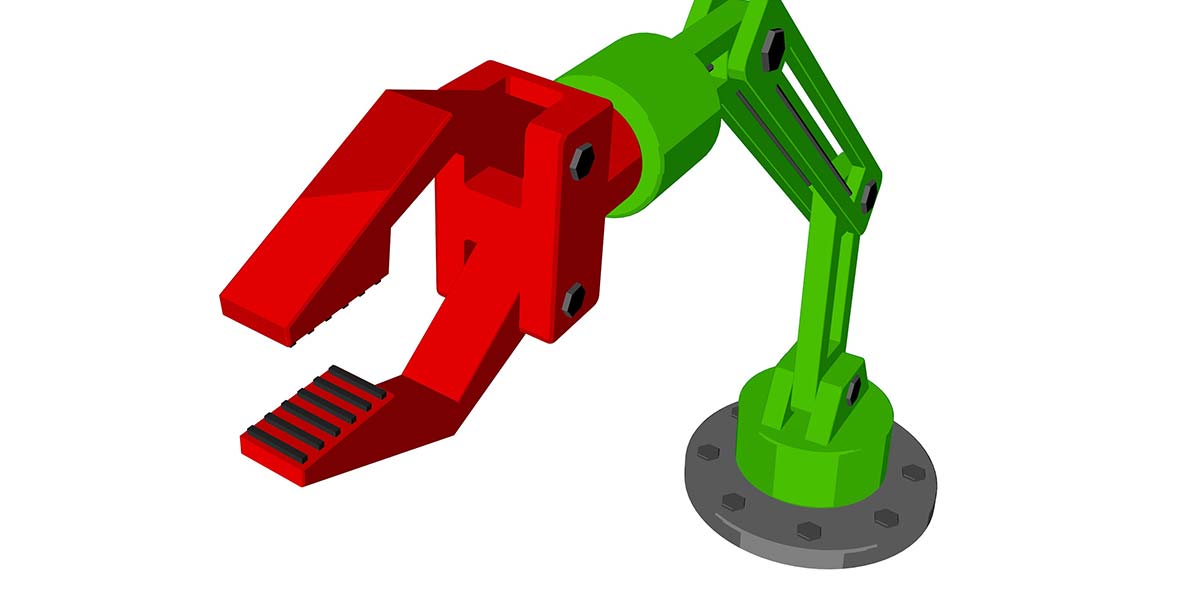
Build Your Own Computer-Controlled Three-Axis Robotic Arm
By V S Rajashekhar View In Digital Edition
Controlling robots using a computer is very easy for hobbyists these days due to the availability of open source hardware and software. The happiest news is that the software is platform independent. It means that you can use it on your Mac OS X, Windows, or Linux computer.
What is my definition of computer-controlled robots? To use a computer in order to control a mechanism/mechanical system with links and joints, of which one or more are actuated by servo motors or other motors. A graphical user interface (GUI) should also be available which allows the user to interact with the mouse or keyboard which replicates in advance a computer-aided design (CAD) model of the physical hardware. Once this CAD model is manipulated, the physical hardware should also perform the same action done by the former.
My plan is to build several computer-controlled robots from scratch in the months to come using less expensive hardware and open source software.
I hope this experience will be helpful in controlling your own robots using a computer. I’m sure this will pave the way for telerobots as well, which means you can control a robot from any part of the world through an Internet connection.
Taking Off to Build Your First Computer-Controlled Robotic Arm
We’ll start with building a three-axis robotic arm. I hope it will be simple as it requires about an hour to build and implement. It requires the following as shown in Figure 1: a hot glue gun and hot glue stick to attach various parts together; a plastic box filled with a heavy substance (sand, for example) that acts as the base of the robotic arm; and a cutter for the thick cardboard which acts as links.
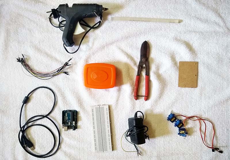
FIGURE 1. The materials required for making the computer-controlled robotic arm.
An Arduino Uno is used for the microcontroller along with a USB-UART cable. A breadboard is used to connect the servo motors with the microcontroller through the power supply. We’ll use three 9g micro servos as joints of the robotic arm.
Building the Hardware
Once you have all the above-mentioned materials, it’s easy to build the mechanical arm and give the circuit connections. The mechanical setup section teaches you step by step to make the mechanical arm. The electronic setup section teaches you the connections for the robotic arm.
Mechanical Setup
As a first step, take a small box and fill it with sand so that it can be used as a base for the robotic arm. Next, fix the micro servo motor to the box as shown in Figure 2 using hot glue.
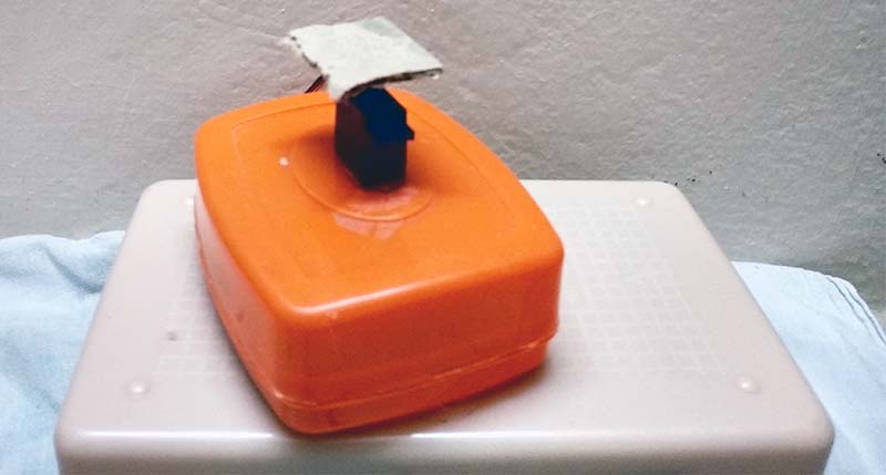
FIGURE 2. The base servo motor is attached to the ground. The square cardboard is attached to its horn.
Over the horn of the micro servo motor, fix a small square piece of thick cardboard using hot glue. The base of the robotic arm is now ready. Wait for it to dry.
Fix the side of the second micro servo motor over the small square piece of thick cardboard as shown in Figure 3 using hot glue. Fix the rectangular shaped thick cardboard on the horn of the micro servo motor again using hot glue. The first axis of the robotic arm is now ready. Wait for it to dry.
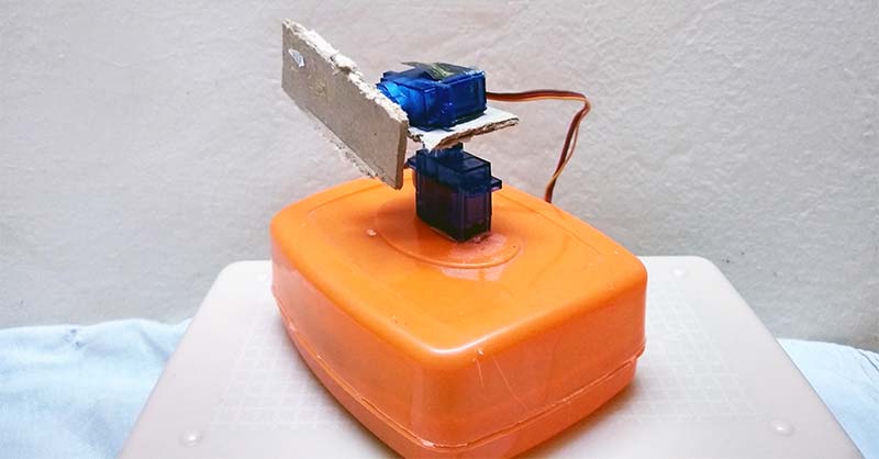
FIGURE 3. The shoulder servo motor is attached to the rotating base. The rectangular cardboard is attached to its horn.
Now, it’s time to fix the third axis of the robotic arm. Apply hot glue to the base of the third micro servo motor and fix it on the second link as shown in Figure 4. Apply hot glue to the horn of the third servo motor and attach the rectangular shaped thick cardboard. This completes the full mechanical setup needed for the robotic arm. Wait for it to dry.
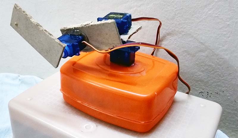
FIGURE 4. The arm servo motor is attached to the rotating shoulder. The rectangular cardboard is attached to its horn.
Electronic Setup
This requires the use of the breadboard, Arduino Uno, and 5V 1A power supply. You can also use the 5V power supply from the Uno board since only one servo motor is going to be used at a time. Follow Figure 5 and give the connections as shown.
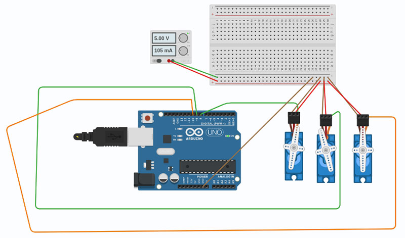
FIGURE 5. The circuit diagram of the servo motors with the Arduino Uno and power supply.
Make sure of the following: pin 8 of the Uno is connected to the base (first) micro servo motor; pin 9 of the Uno is connected to the shoulder (second) micro servo motor; and pin 10 of the Uno is connected to the arm (third) micro servo motor.
This completes the electronic setup required for the computer-controlled robot.
Working on the Software
Microcontroller
You can download the Arduino software for your operating system from https://www.arduino.cc/en/Main/Software.
The code for the Uno is located at Examples > Firmata > StandardFirmata. Upload this code to the Arduino microcontroller. Make sure that the power supply to the motors is turned off while you upload the code. If everything goes well, the microcontroller should be ready to receive signals from the computer. The Arduino should always stay connected to the computer from now on.
Graphical User Interface
You can download the Processing software for your operating system from [url=https://processing.org/download]https://processing.org/download[/url]. Install and open it.
Open the file “Three_Axis_CAD_Slider.pde” that is included in the article downloads. It’s also available at https://github.com/rajashekharvs91/Computer-Controlled-Robots/blob/master/three_axis_robot.zip.
Look for this line:
arduino = new Arduino(this, “/dev/ttyACM0”, 57600);
Replace “/dev/ttyACM0” with the port name to which your Arduino is connected to. Do not forget to use the double quotes!
Now run the Processing program and you should get the screen as shown in Figure 6.
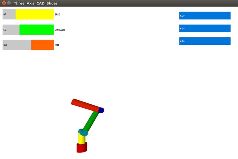
FIGURE 6. The GUI of the robotic arm used for control.
You are now ready to control the three-axis robotic arm. Move the sliders on the top left corner and you’ll see the mechanical setup moving.
You can also connect a camera and view the output on the screen as shown in Figure 7.
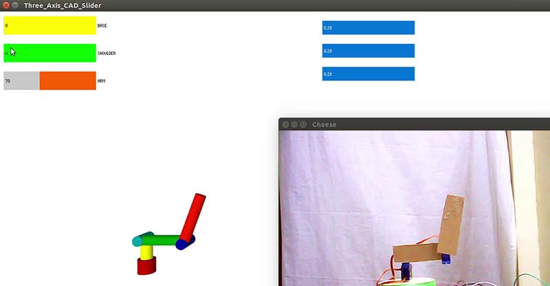
FIGURE 7. The GUI with the feedback of the physical hardware.
Conclusion
I hope this quick and easy project will whet your appetite to expand your experimentation into computer-controlled robotics. You can watch the robotic arm in action at https://youtu.be/fZdbQB4zLcU. SV
Article Comments