
Build a Simple Micro-Ohmmeter
By Dennis Vollrath View In Digital Edition
This project provides the ability to measure those very low value resistance values such as motor windings, servo connectors and similar items.
I go back to the electronics stone age where a Wheatstone bridge was required to measure resistance values of less than a few ohms. Back in those days, Wheatstone bridges were extremely expensive. As a comparison, this project can be built at a cost of a few meals at your local fast food place (not counting the battery).
So, what parts are required?
This project has evolved from a rather complex circuit to the current design. The basic circuitry is rather simple using only an Arduino Nano, an MCP3424 analog-to-digital converter (ADC), a 128x64 OLED, a six ohm 1% resistor, and a 0.1 ohm 1% resistor. That’s it.
Add to these components several more resistors, capacitors, and zener diodes that serve to protect the ADC input from any potential voltage surges, such as those surges that occur when measuring motor winding resistances. Also, a couple more resistors provide the ability to display the internal battery voltage on the OLED display.
What is a MCP3424 ADC?
(This series of ICs has one input or two input versions.)
This ADC is rather useful for a wide variety of projects. This low-cost chip has programmable gain inputs from 1X to 8X, along with its programmable resolution from 12 to 18 bits. The MCP3424 also includes a high precision internal voltage reference. At maximum sensitivity, it only requires around 0.06 volts for full scale input.
How It Works
The first prototype was built on a perf board; something that has worked quite well. Later on, I designed a (printed circuit board (PCB) for this micro-ohmmeter project. As is required for this type of circuit, the resistance value is measured using the four-wire connection to the resistor under test.
The Arduino Sketch software controls both the OLED display and the MCP3424 ADC. The circuit design applies a test current of about 1.2 amps, provided by the two-cell LiFe 6.6 volt battery through R4: a five ohm 1% resistor to the resistor or circuit under test.

PCB layout.
The MCP3424 uses its channel 4 input to measure the voltage across R1 — the 0.1 ohm 1% resistor. From that voltage measurement, the actual test current to the resistor under test is determined.
Next, the ADC uses its channel 3 input to measure the voltage drop across the test resistor. A standard resistance formula is used in the Arduino Nano sketch to calculate the resistance value. The sketch simultaneously displays the resistance values in micro-ohms, milli-ohms, and ohms as shown in the photos. If desired, the range of this meter could be altered by changing R1 and R4 along with the required modifications of the sketch.
The micro-ohmmeter automatically steps though four ranges while reading in the low micro-ohm range to the full scale value of two ohms. This meter can easily measure the resistance of a one inch long piece of common #16 wire (it’s 317 µohms). I’ve built up five of these meters so far. All of them measured the same resistor within a percent or two. The sketch does allow exact calibration of the meter against a known accurate resistor of around one ohm.
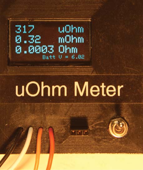
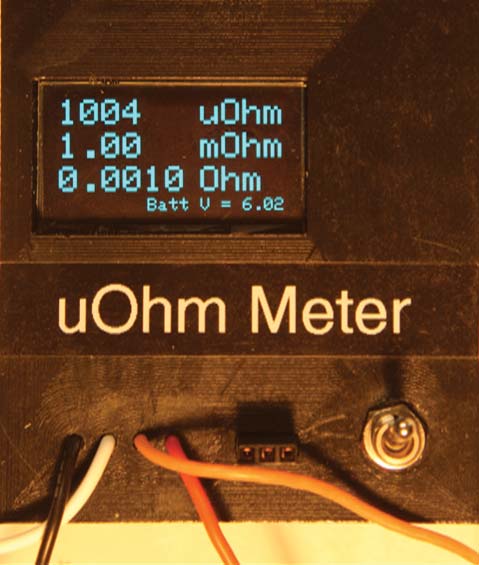
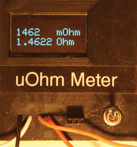
These photos show the measurements of a one inch piece of #16 wire, a four-wire 0.001 ohm 1% resistor, and a 1.5 ohm 5% resistor.
As previously indicated, resistors R2 and R3, zener diodes ZD1 and ZD2, and capacitor C2 protect the ADC input against any potential voltage surges. Resistors R5 and R6 along with capacitor C1 allow displaying the battery voltage on the OLED display.
Don’t use those higher powered five volt zener diodes in this circuit! Some of those zeners have a rather poor “knee” in their voltage/current curve that could affect the accuracy of the micro-ohmmeter.
One percent resistors are required for both R1 and R4. Using a standard 5% resistor as R4 will cause minor drifting of a half percent or so in the measured value of the test resistor as the 5% resistor heats up during a resistance test.
Also, the micro-ohmmeter pulls around 1.2 amps out of its battery, requiring a two-cell LiFe 6.6 volt battery of around 500 mAh to 1,000 mAh for power. Alkaline cells will cause slight drifting of the measured test resistor value since the alkaline cells drop in voltage during a measurement run on a resistor.
CAUTION!
NEVER conduct a resistance measurement of a resistor using only the USB port of the Nano circuit for power. This will damage the voltage regulator of the Nano by current flowing from the PC USB port, reversing direction through the Arduino five volt regulator, R4, and the test resistor.
THAT CAN BLOW THE NANO’S FIVE VOLT REGULATOR.
Construction Notes
As mentioned, this project can easily be built on a readily-available perf board with the following cautions.
First, run the ADC channel 3 inputs directly to the resistor under test.
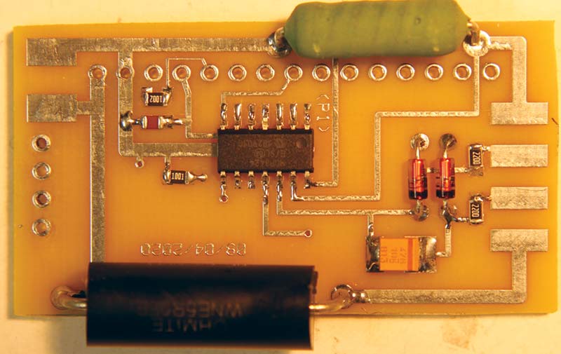
The top view shows all the components required for the micro-ohmmeter. The only component on the back side of the PCB is the OLED display. The sole function of the two resistors, two zener diodes, and the 47 µF capacitor on the left side of the PCB is to protect the ADC input against over-voltages. The right-hand resistors allows the meter to display battery voltage.
Second, run the ADC channel 4 inputs directly to resistor R1. Do not connect the ADC negative inputs to any common negative circuit carrying current such as the negative DC input of the Arduino Nano.
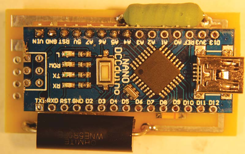
Note the view of the PCB with the Nano, along with the four-wire test leads and the red and black wires leading to the two-cell 6.6 volt battery that powers the meter. Note that Nano pins A4 through Vin are soldered. The remaining pins are not connected.
The MCP3424 will readily respond to the milli-volt voltage drops across any common negative wiring between the ADC and the Nano DC power circuits.
Check out the schematic for the micro-ohmmeter.
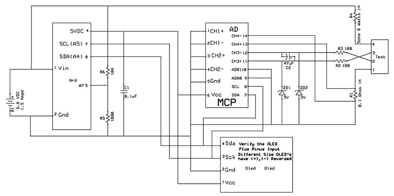
Schematic.
The only precision components required are the 5 ohm and 0.1 ohm 1% resistors.
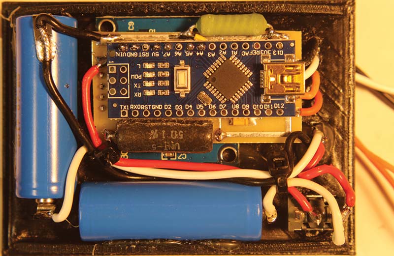
The final product is shown installed in a 3D printed case. The two blue items are a pair of Li-ion 400 mAh battery cells.
I hope you find this unit measures up to your low resistance value needs. SV
Parts List
Arduino Nano Microcontroller
128x64 OLED
MCP3424 ADC, Digi-Key
0.1 ohm 1% Resistor, Digi-Key #PPC3D.10CT-ND
5 ohm 1% Resistor, Digi-Key #WNE5R0FETCT-ND (use 25 watt resistor for heavy duty use)
180 ohm, 1K, and 10K Resistors, a 47 µF Cap, and a 0.1 µF Cap; 1K and 10K should be 1%.
Five volt Zener Diodes Digi-Key #1727-6149-1-ND
6.6 volt Rechargeable Battery Tower Hobbies
Switch
Arduino MCP34xx Library Link https://github.com/stevemarple/MCP342x
Sketch Site https://www.rcgroups.com/forums/showthread.php?3693675-Vollrathd-s-MicroOhm-meter-Sketch#post45306839
Downloads
202002-1-Volrath.zip
What’s In The Zip?
Source Code
PCB File
Schematic Files
SwitchIR Meter Instructions
SwitchIR PDF Files
Article Comments