Build a Drone Crash Beacon
By John Leeman View In Digital Edition
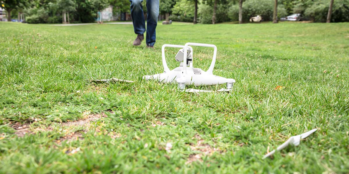
I’ve been toying with ideas about using drones to help with agricultural evaluation, but keep having the same vision of my quad plunging down into a corn field. After hours of searching, I doubt that I would be able to find it (there are such things are corn mazes, remember). In fact, it would probably sit out in the field until harvest and then be mercilessly ground up by harvesting equipment. Who knows what the aging and weathered battery would do. Not a situation I want to be in. So, I’ve made a beacon that will make finding a downed copter much easier.
Introduction
Many vessels are equipped with emergency beacons. Aircraft and seafaring vessels both have position beacons and even an infamous “black box” that records state data. I wanted a simple beacon that would help me find my downed quad in the simplest way possible.
First, I considered a GPS beacon that would send a text message with the final resting coordinates via the cell network. That seems over-complicated and assumes that there will be cell coverage — not always a given in remote areas. It also is a complex enough system that several things could go wrong, including the shearing of an antenna during a crash.
Next, I considered a Wi-Fi solution that would just require me to be near the vehicle. There are still concerns about the antenna surviving the crash, and I would need to be pretty close to the craft in the first place. It also consumes a lot of power, meaning that it wouldn’t be a beacon for very long on a small battery.
Large batteries add weight and I want to remain independent of the quad’s power system in case that is what caused the crash. With that solution out as well, I decided that something following the KISS (Keep It Simple Stupid) principle would be the best.
The solution I settled on was indeed dead simple: a piezo buzzer. Once the quad detected that it was in free fall, I wanted a loud tone set to be broadcast every few seconds. Sound carries surprisingly well and our ears are great direction finders.
I couldn’t quite leave the system that simple, so I thought it would be nice to have a quick and easy arming mechanism, a visual status indicator, and a low battery warning. With these features in mind, I needed to figure out how to detect free fall and then get to work.
Detecting a Crash
The first order of business was determining when the beacon needed to be activated. I didn’t want it to accidentally turn on during normal flight, requiring a trip back to home base to turn off the beeping. Failure to activate during a crash would be just as bad.
A few sensors come to mind. I could sense the altitude and activate when the rate of decent exceeded some threshold (also known as the derivative for those versed in differential calculus). This would most likely work, but requires measuring the surface pressure, filtering noise on the signal, and a few other annoyances. I could use a gyro and trigger on high angular velocities, but not all crashes have significant spin components to them.
I finally settled on the accelerometer. The one thing most crashes will have in common is a period of free fall. In fact, I think it would be pretty hard to have a powered downward acceleration (flying with the quad upside down) that is stable for any length of time. Even if you hit an obstacle, the subsequent descent is in free fall.
Now that we know an accelerometer is what we will use, we need to figure out how to interpret the data it is giving us and determine when the craft is falling out of the sky. To do that, we need to first understand exactly what acceleration is and what the accelerometer tells us about it.
Fundamentally, acceleration is the rate of change (remember, that means derivative) of velocity, which is the rate of change of position. Acceleration is measured in m/s2 (often said as meters per second per second).
The largest acceleration that we all experience every second of every day is the acceleration of gravity. Gravity has a “constant” acceleration of 9.8 m/s2 on average at the surface of the Earth. It is what holds us down in our chairs and fights us on the stairs every morning.
Sometimes we measure accelerations with respect to gravity using the unit of “gs.” So, 1g is 9.8 m/s2; 2g is 19.6 m/s2; and so on. Since gravity is a large and constant signal of 1g that points straight towards the center of the Earth, it’s what accelerometers measure.
Essentially, accelerometers tell us which way is down (Figure 1).

Figure 1: Accelerometers will report the accelerations they experience in the X, Y, and Z directions. Knowing that gravity always accelerates things towards the Earth’s center of mass (straight down for this practical application), we can resolve the relative orientation of the sensor.
The flight controller on your quad uses an accelerometer (among other sensors) to keep itself level and stable.
So, how does knowing the direction of down help us out? Think about an object in free fall. The object is being accelerated by gravity toward the center of the Earth. What acceleration would an accelerometer attached to this free-falling object measure? Zero!
In fact, if you’re going fast enough when you are in free fall, we call it orbit, and you’re on the international space station where things seem weightless because you’re all falling towards the Earth at the same rate that the Earth is falling away from you.
Great. So, we look for when our accelerometer reads zero and then trigger, right? Well, not quite. First of all, it won’t read exactly zero because of pesky things like air resistance and other approximations we made in the spherical chicken approach above.
The other complication is that most accelerometers measure acceleration in three directions (X, Y, Z) that are fixed with respect to the case of the accelerometer. That’s great for determining your orientation, but not so great unless we only want things to work when falling in a single orientation.
The most robust way to do this is to calculate the magnitude of acceleration being measured, or the Euclidean distance (Figure 2).
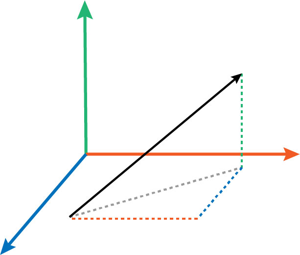
Figure 2: The measured X, Y, and Z accelerations (red, blue, green, respectively) can be added to produce the total acceleration vector (black). The length of this vector is the magnitude of acceleration being experienced by the sensor.
Luckily, that’s a pretty straightforward formula. We can then set a threshold and compare our acceleration magnitude to it, then decide if an alarm is necessary.
Hardware
My first reaction given this set of desired functionalities was to open up KiCad and cut a PCB (printed circuit board). I would need to include a microcontroller, programming interface, LED(s), accelerometer, and buzzer.
Given that I wanted to rapidly build and use this crash beacon and only needed one, that seemed like overkill. I went digging through my box of dev boards and found the perfect platform: the LightBlue Bean (Figure 3).
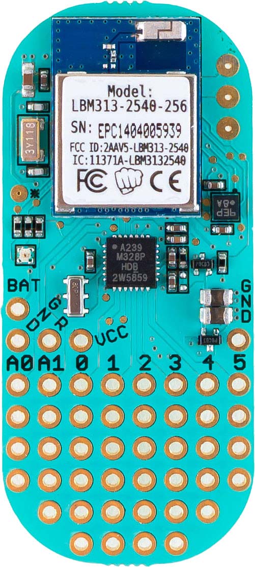
Figure 3: The LightBlue Bean is a nice compact development board with a microcontroller, accelerometer, temperature sensor, RGB LED, and Bluetooth module. (Image courtesy of PunchThrough.com.)
I first heard of the Bean back when Punch Through Design (https://punchthrough.com) was Kickstarting it. I bought one and used it on an early version of my drone atmospheric sounding system. You can read about those early adventures at www.johnrleeman.com/2015 /07/30/drone-sounding-prototype or follow the build of the final version of the system here.
The Bean is equipped with a microcontroller, Bluetooth module, RGB LED, accelerometer, prototyping area, and coin cell power. Perfect!
Another interesting feature of the Bean is that it’s programmed over Bluetooth via the regular Arduino IDE (integrated development environment) or the Bean Loader iOS/Android apps.
I recently acquired a 12.9” iPad Pro and wondered if I could take a simple project from start to finish with only the iPad (including writing this article).
The only things the Bean didn’t have onboard were the buzzer and the arming mechanism. I again found a surplus piezo buzzer in my junk bin and soldered it onto the prototyping area. I connected the positive terminal of the buzzer to pin 3 of the Bean.
Any pulse-width modulation (PWM) capable pin will work (Figure 4).
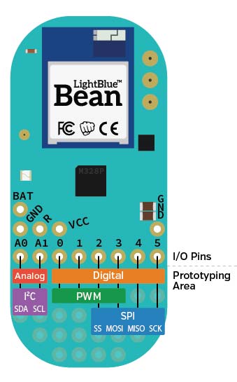
Figure 4: The Bean offers four PWM capable pins, with six digital pins. (Image courtesy of PunchThrough.com.)
I then connected the negative terminal to ground through a 1K resistor (Figure 5).
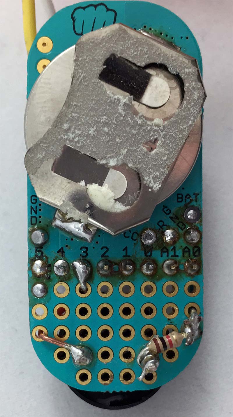
Figure 5: I added the piezo buzzer to the prototyping area and tucked the resistor to ground away under the PCB. This Bean has been used in a lot of temporary/ demonstration projects and the PCB has seen a few better days.
The arming mechanism is just going to be a high/low state detection on a pin. I soldered a wire to pin 4 of the Bean and the other to ground. For testing, I just left them as flying wires since the mounting problem hadn’t been thought about yet (Figure 6).
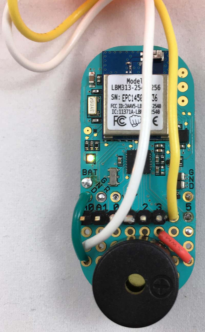
Figure 6: Arming wires are attached to ground and pin 4.
In terms of actual hardware assembly, that’s it! I like that there are only a few connections to make as they would be the first things to go during a hard crash.
Firmware
The firmware is written in C++ like any other Arduino project, but we have some additional functionality through the Bean library. You can learn about these through the reference on Punch Through’s website or by exploring the macros menu in the apps. Being able to insert the correct call from a menu makes development run very fast with fewer fat-finger typos.
Like any microcontroller project, we should start out by designing a state machine diagram. In this case, things are pretty simple.
We have an initialization, check for free fall, and alarm state. We could add a wait state in there if we wanted, but this program is simple enough we won’t follow a strict design pattern like we have in the past.
We will handle all the initialization tasks in the setup function as it only runs when the microcontroller powers up. In this state, we set the range of the accelerometer (to ±4g in this case); enable the low g motion event (more on that later); make sure the RGB LED is off (0, 0, 0); set the buzzer pin to be an output; and set the arming pin to be an input with the internal pull-up resistor enabled (Figure 7).
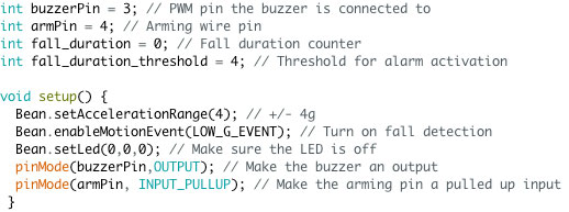
Figure 7: This setup function runs when the unit is powered up, and takes care of housekeeping like configuring the accelerometer and GPIOs.
In the main loop that runs over and over again, the first thing we need to do is check if the system is armed. Remember that the arming pin is pulled up, but our “remove before flight” plug connects it to ground. So, if the pin is low, we know the system isn’t armed (i.e., the plug is still inserted) and we can sleep for a while.
In this case, I decided to sleep for one second as response time isn’t critical. Right off the bat, you should notice that I didn’t use the delay function as you normally would in an Arduino sketch. Delay simply counts until some amount of time passes, but using the sleep function from the Bean library, we are actually putting the microcontroller into a low power state. That’s crucial to making the battery last a long time (Figure 8).
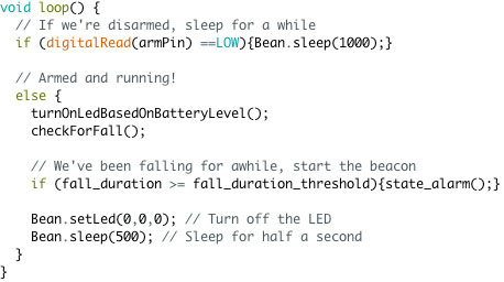
Figure 8: The main loop handles any state transitions, as well as determining if the system is armed or sleeping.
If the pin is high, that means the flight plug has been pulled and the system is armed. We first turn on the LED based on the battery level using the getBatteryLevel function. This function returns the battery level as a value between zero and 100.
If the battery is at or below 50%, we will make the LED yellow. At or below 20%, it will be red, and above that, it’s green (Figure 9).
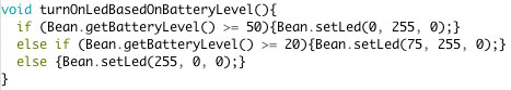
Figure 9: This simple function lets us know when we need to be adding a spare battery to our flight bag by indicating three states of charge with the onboard LED.
Next, we need to determine if we’re falling. You will notice that I’m not reading the X, Y, and Z accelerations and calculating the vector magnitude. This particular accelerometer (along with the Bean library) allows us to just look for high acceleration events, any movement, or low acceleration events.
A LOW_G_EVENT is a free fall detector! All we need to do is check if there is a low acceleration event detected.
If we are in free fall, we add to a counter called fall_duration that keeps track of how many consecutive queries have resulted in a free fall determination. This is a way to make sure we didn’t get a bad reading or that we happened to read the accelerometer just as a wind gust was swatting us around. If there is not a fall detected, we make sure that this counter is set to zero (Figure 10).
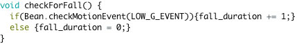
Figure 10: If the unit is in a free fall state, this function will increment the fall duration counter; otherwise, we reset it.
If the fall_duration counter is at or greater than our threshold, we have decided that we are really in a harmful free fall and go to the alarm state. Otherwise, we turn the battery-indicating LED off and go back to sleep for a half second (refer back to Figure 8).
The alarm state is itself a semi-infinite loop. The program immediately enters a while(true) loop that turns on the LED to a red state (maybe you could see it after dark?), then produces a series of three sets of high-low tones using the tone function. The first tone is 880 Hz for a second, then a 100 ms pause before a 440 Hz tone. After that, the LED is turned off.
Lastly, we check if the arming plug has been plugged back in. If so, we have found our drone. We then break out of the infinite loop, return back to the main loop, and get ready for another flight without a need to re-power the system.
There is a five second sleep between the loops of the alarm state to help save battery life (Figure 11).
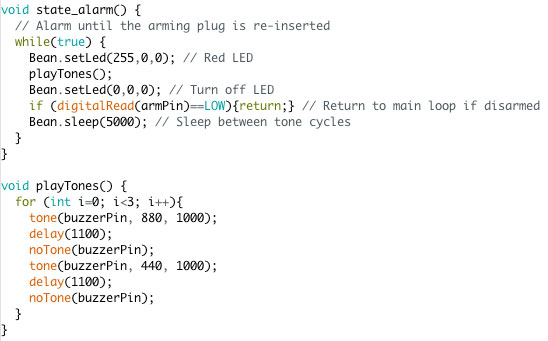
Figure 11: The alarm state turns on the LED and plays the tones before going to sleep. Once the arming connector is replaced, the program returns to the main loop.
Generating tones more frequently than that is unnecessary and wastes power.
So, overall, the firmware is pretty straightforward. Developing on iOS was a very interesting experience. I like the menus of Bean specific functions, but found the integrated editor slightly frustrating as the auto-indentation did some strange things (Figure 12).
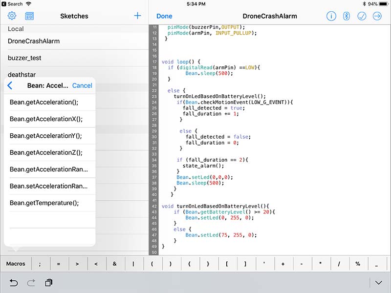
Figure 12: Developing on iOS was a surprisingly pleasant experience, except for the strange editor indentation behavior. I liked not needing to carry a laptop and USB cable around to be able to develop wherever I was.
I ended up cleaning up the code in another editor after I had it working. You can get the firmware and even see its evolution from hacky working code to a nicer and well commented code in the downloads or at my GitHub repository (https://github.com/jrleeman/CrashBeacon).
You can, of course, develop on a desktop/laptop using the Arduino IDE. The only change to the normal workflow is downloading and installing the Bean Loader tool and associating it with your Arduino IDE. Then, you set the Bean as the target board type, click compile/upload, and the binary is made available to the Bean Loader application. It can then be uploaded to the Bean from there (Figure 13).
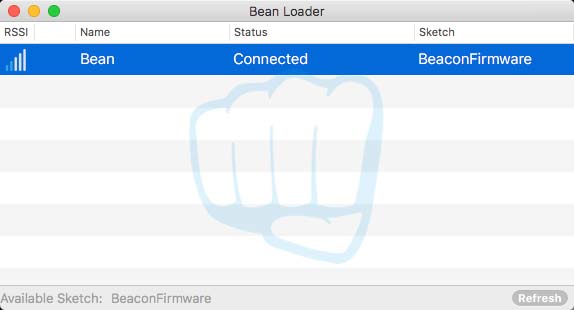
Figure 13: The desktop Bean Loader makes uploading firmware created in the traditional Arduino IDE easy.
Testing
Testing the system is a bit tricky as I don’t exactly want to crash a quadcopter for the sake of it. As a first approximation, I simply reduced the trigger threshold to two events, so that tossing it up in the air would produce enough free fall time to trip the beacon. Just don’t forget to change the threshold back before putting it on your quad!
With the arming wires connected, there should be no activity on the Bean. When the wires are separated, the system should arm and you will see the LED flashing with the battery status. If you toss the beacon into the air, it should alarm by the time you catch it.
To shut off the alarm, hold the arming wires together for a few seconds. You should now be back to the beginning state where you can arm the device. If you run into trouble, double-check your connections and that you updated the pin numbers in the sketch if you modified your layout.
Installation
Mounting the beacon on the drone poses an interesting question. Is this a permanent component or can it be moved from vehicle to vehicle? You certainly could mount it onto your quad frame with double-stick tape, zip ties, or Velcro™ with various levels of permanence. This would let you mount the arming connector to the drone frame as well.
Another option is to make a small self-contained unit in something like a pill bottle or 3D printed enclosure. Just be sure to leave holes for the audio to clearly project!
I opted to make a simple 3D print that held the Bean and a radio microphone connector for the arming connector (Figure 14).
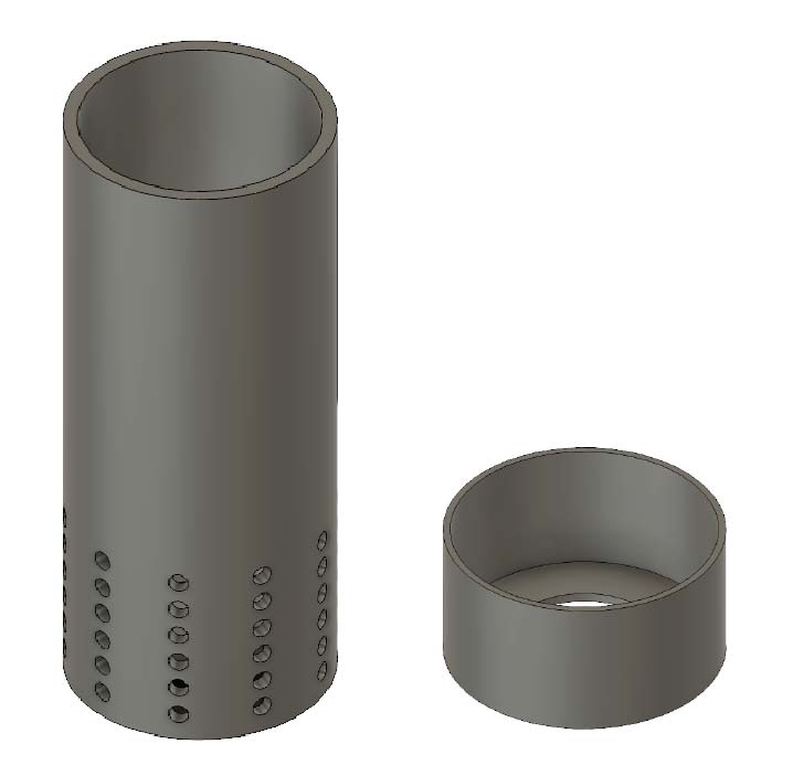
Figure 14: The enclosure for this project prints in 1-2 hours depending on your settings, and is a press-fit.
You could use anything you have on hand; an XT60 comes to mind as a good solution. I just made a shorting plug to use to disarm/reset the system (Figure 15).
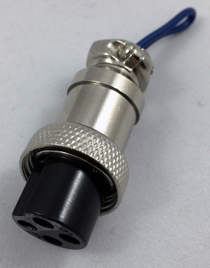
Figure 15: A radio microphone plug makes a great and secure arming plug. The security of the threaded attachment makes sure it will not pull out and begin going off in my toolbox or flight bag. I shorted pins 1 and 4 together.
You can even buy a “remove before flight” tag from Amazon to remind yourself if you so choose (http://amzn.to/2wUWTiG). You can get my 3D print files at the article link or project repository.
The system doesn’t need to be rigidly affixed to the quad, but double-stick tape is my general answer to such problems. It could be attached with a zip-tie as well.
Finally, I tested the system on an inexpensive toy and verified that I like the response. Overall, I was very happy with the results for a quick Saturday project!
Closing Thoughts
Now that you have a locator beacon (Figure 16), it should be easier to find your downed craft in the event of a crash. I haven’t totally ruled out the idea of a GPS/cell beacon at some point.
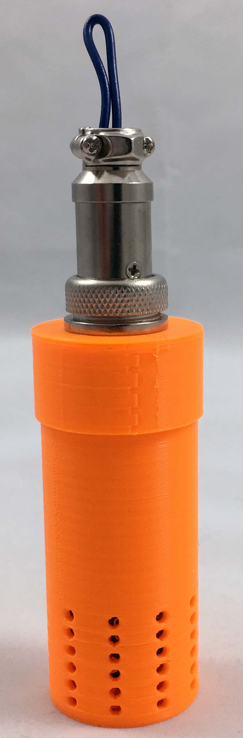
Figure 16: The final product is bright, sturdy, and small. The internal LED makes its way through the relatively thin shell and the sound carries out of the enclosure very well.
I also would consider adding a larger buzzer and/or light, but would then need to add additional battery capacity.
Finally, I’m considering extending the functionality to include fall triggers for things like parachute deployment. Until next time, fly safely. SV
Article Comments