Build a Diff-Drive Using TYT Manufacturing
By James Louis View In Digital Edition
Working from my home shop during a large part of this pandemic has taught me a lot about time, supply chains, and manufacturing techniques. For example, when the strap broke on one of my few N95 respirator masks, it made no sense to throw it away because these were out of stock for almost a year. I learned to use Lord 310A/B two-part epoxy to attach replacement straps on the mask by using a revolutionary new manufacturing technique: Take Your Time (TYT) Manufacturing.
By only attaching the right-side straps, then waiting 24 hours and repeating for the left side, it would take two full days to restore one mask. Although a turn-around time like that would have been unacceptable just two years earlier, this made perfect sense now that I had extra time each day thanks to not driving to work.
We Don’t Need No Stinking Frames
Many differential-drive robot kits (two driven tires with a ball caster) come on boats from far away. In fact, the US has purchased so many injected molded and stamped consumer products from China, they had to widen the Panama Canal just to satisfy our national appetite.
Although one little robot frame is not even a drop in the shipping container, it got me thinking. Could a person use TYT to build a frameless diff-drive robot? Why not? We live in crazy times.
So, this article will be a kind of Part 2 to my previous one, Reconsidering the BeagleBone Blue, from Issue-5 2020 of SERVO Magazine.
In place of a frame, I’ll be using a trinity of adhesives: epoxy, silicone sealant, and super glue. A common rule for all of these is they need to be used on oil-free surfaces that have been cleaned with Acetone™.
What You’ll Need
Hardware:
- Microcontroller from Reconsidering the BeagleBone Blue
- Horizon Hobby E-Flite EFLB13002S20 LiPo Battery
- Horizon Hobby VNR17043 Balance Lead Extension Cable
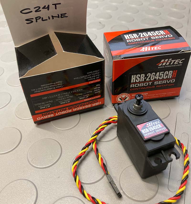
- Hitec HSR-2645CRH Continuous Rotation Servos
- ServoCity SW1875SH C24T Spline Tires
- Pololu Ball Caster (Item #952)
Applying TYT Manufacturing
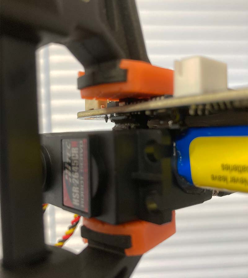
Day 1: Clean the gluing surfaces of your servo motors with Acetone, then clamp them together with silicone sealant as shown in Figures 1-3.
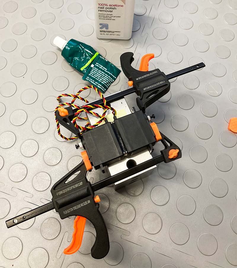
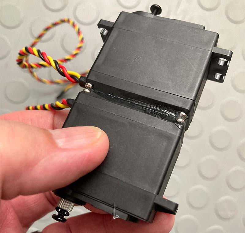
Figures 1-3: Gluing the servos.
Day 2: Similarly clean the bottom of the LiPo battery and the contact area of the servo motors. Place them on a flat surface (I’m using a 1-2-3 block) protected by a Post-it Note as seen in Figures 4-7.
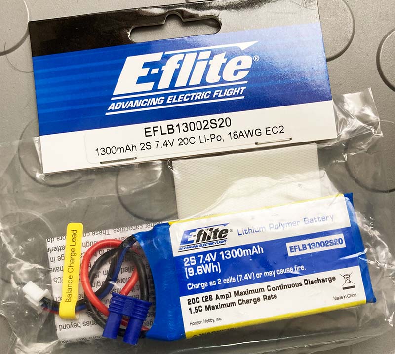
Figure 4. Gluing the battery.
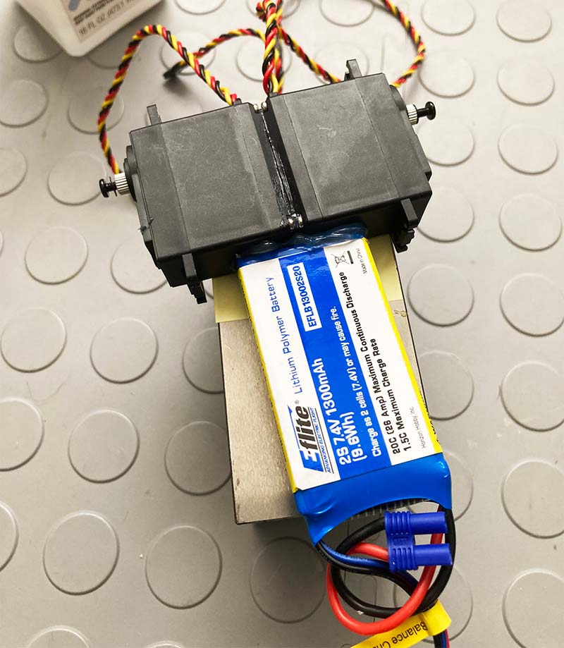
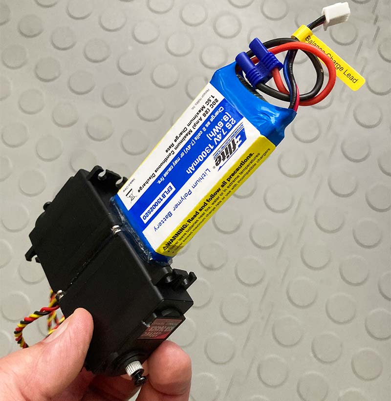
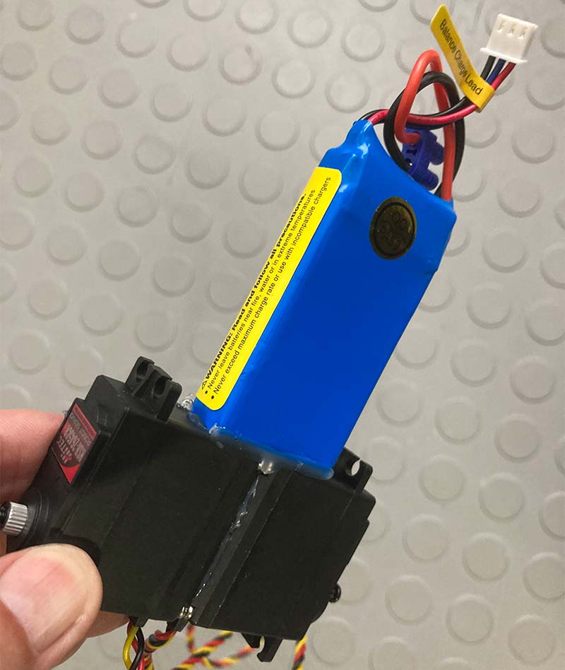
Figures 5-7. Gluing the battery.
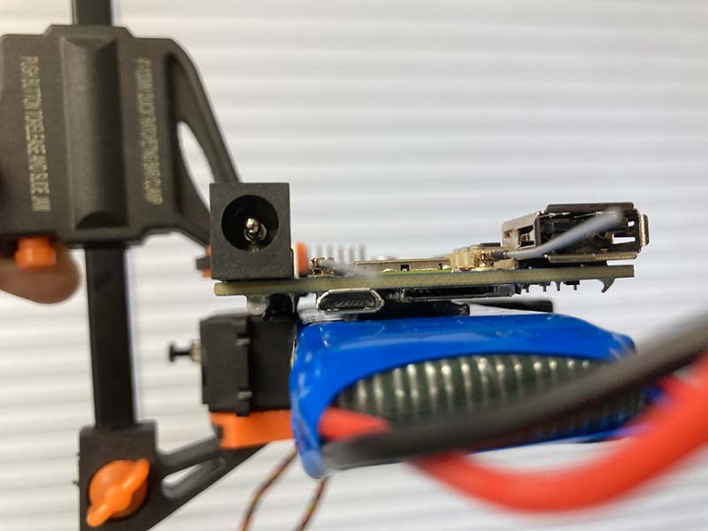
Day 3: Clean an area along the center of the battery and the top of the motors. Take your BeagleBone Blue (BBBlue) and apply a generous landing strip of silicone sealant from the motor seam to the top of the battery, and another strip along the bottom of the board.
Put a dot of super glue on the flat component in the corner of the board and gently clamp it so the whole board moves into a parallel position with respect to the battery. Be sure there is enough silicone sealant to form a bridge as seen in Figures 8-11.
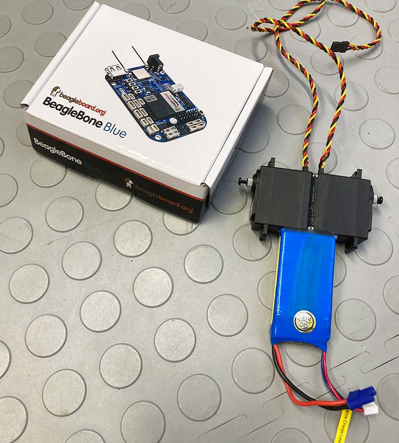
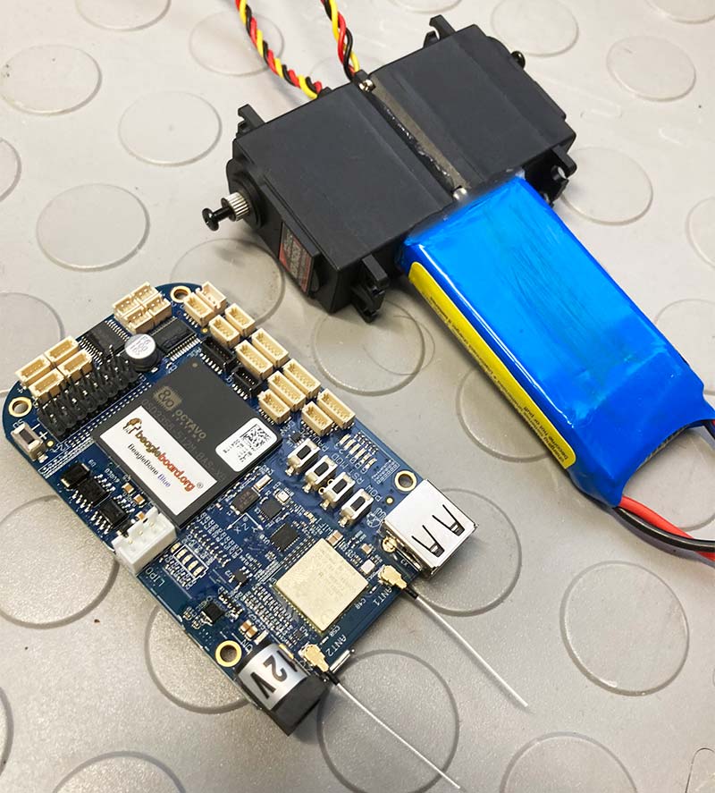
Figures 8-9. Unboxing the BBBlue.
Figures 10-11. Gluing the BBBlue.
Day 4: Attach the tires (Figure 12).
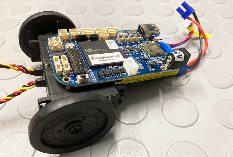
Figure 12. Attaching the tires.
Super-glue your ball slide to the bottom of your battery as seen in Figures 13 and 14.
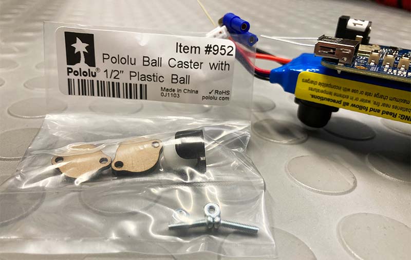
Figures 13-14. Gluing the ball caster.
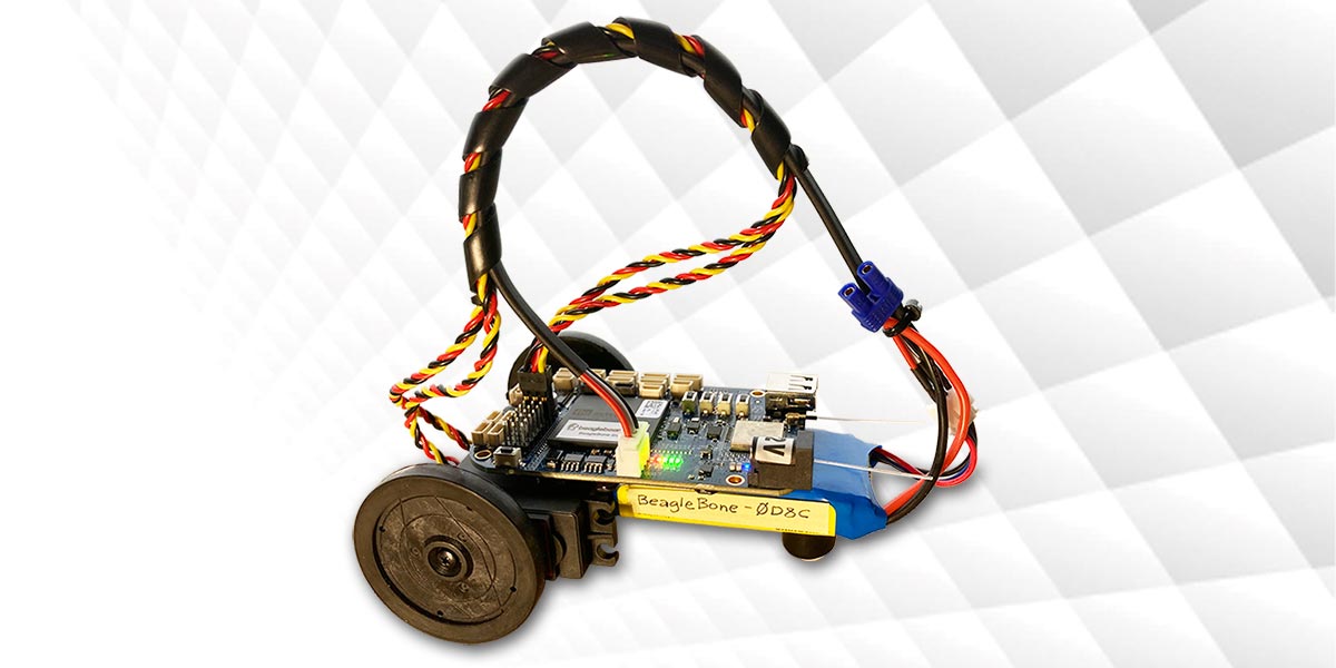
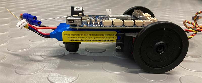
Day 5: Pick up your creation and notice how rigid the structure is because of your care and patience. You have successfully built a frameless differential-drive robot using the power of TYT manufacturing!
Powering Up and Communicating
From my previous article in Issue-5 2020, go to Strawson Design Robot Control Library > Getting Started for detailed instructions on how to Flash the board.
Begin by using the SD Card Formatter and Balena Etcher software programs on your Windows PC to create the micro SD card which is used to write an image onto the BBBlue. When Balena is done, remove the micro SD card from your PC.
Now with the BBBlue still off, insert the micro SD card into its slot (Figure 15).
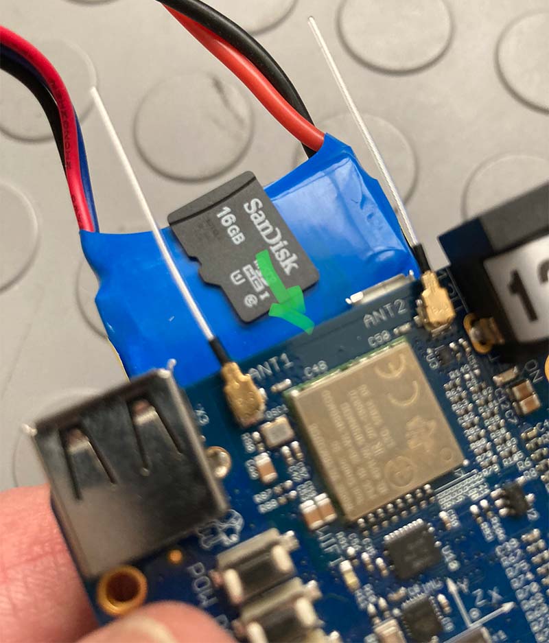
Figure 15. Inserting the micro SD.
While holding down the button on the lower-left of the BBBlue, plug in the power supply, and then the lead extension cable and battery.
Continue holding the button (it takes a while), but once you see the beautiful “ping pong” pattern on the upper row of LEDs, you can release it. Now, wait for the board to power itself off (this also takes a while).
Unplug the power and battery and remove your micro SD card. Careful! It’s easy to forget this last step!
Second, grab a copy of the book BeagleBone Robotic Projects - Second Edition, published by Packt and follow pages 13 to 30 about connecting to the BBBlue.
Here, you’ll use a micro USB cable plugged into the underside of the board (don’t use the BBBlue bigger USB port) and the third software on your PC called PuTTY.
Option #1: Follow the book to connect via a serial COM port, or if you get an error like I did (see Figure 16), use Option #2.
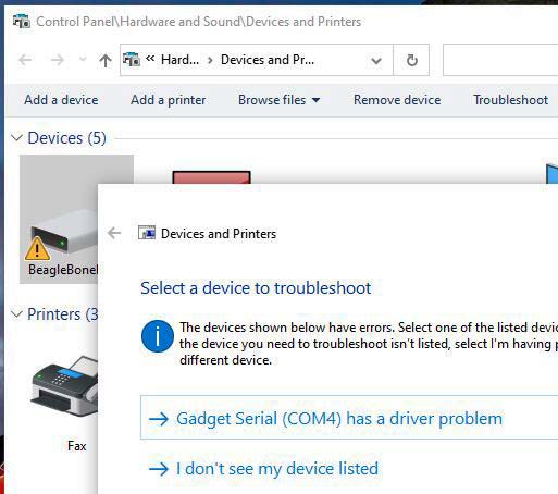
Figure 16. Beaglebone Device Manager problem.
Option #2: Use an SSH connection by typing the USB BBBlue port 192.168.7.2 into the PuTTY field (Figure 17).
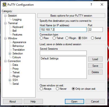
Figure 17. The PuTTy workaround.
Either way, a terminal window will open (say Yes to the warning shown in Figure 18).
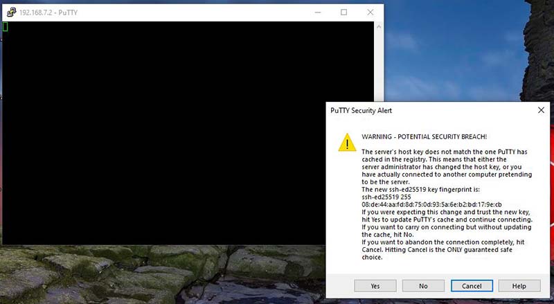
Figure 18. A warning you say “Yes” to!
Log in as “debian” and enter the password “temppwd.” You should be at page 21 of the book at this point. Now, follow the section in the book that enables WLAN. Here is where you’ll need your Wi-Fi password. It’s pretty involved, but the book is very clearly written.
Now every time you ant to communicate with your BBBlue, you can just connect to it using Wi-Fi from your Windows PC using “ BeagleBone” for the network security key. No more micro USB cable.
You may need to bounce between the book and the website Robot Control Library (http://www.strawsondesign.com/docs/librobotcontrol/index.html; Figure 19).
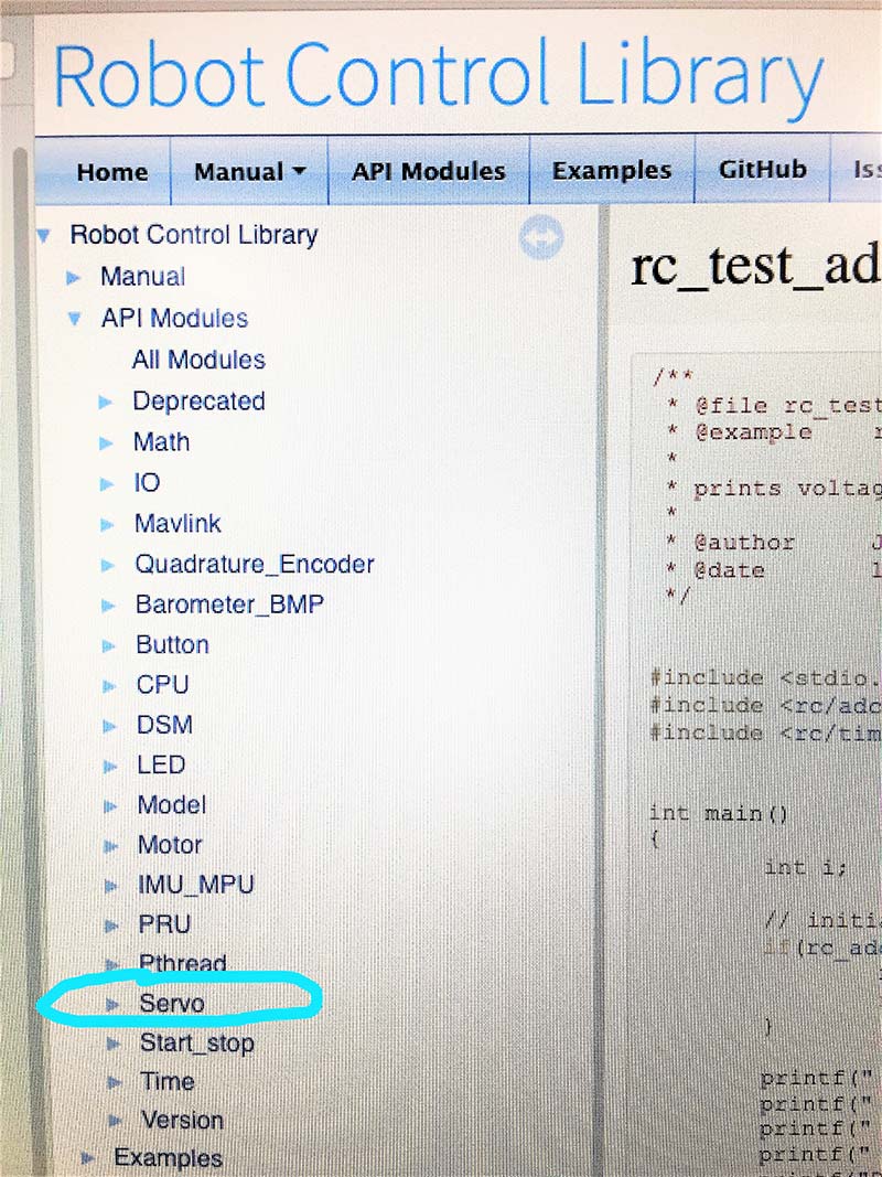
Figure 19. Servo APIs in the Robot Control Library.
At this point, your BBBlue should be easy to power up and wirelessly communicate with using PuTTY in a terminal window of your Windows PC. To test communication, it’s a good idea to run your servos (see Figure 20).
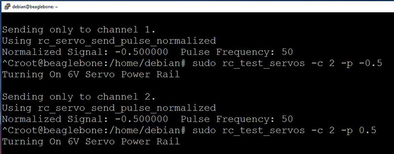
Figure 20. Testing your servos before programming.
In Chapter 3 of the book (page 67), the author describes a very similar robot that uses DC motors rather than continuous rotation servos. The program is in C++ just like the website uses. The code on pages 76 and 77 is a great template for this project, but we’ll need to modify it for our purposes.
You’re now ready to edit the program on page 76 of the book to correct an LED syntax error and to replace the DC motor commands with servo commands for this diff-drive robot.
Here’s where some knowledge of basic Linux commands and the built-in editor called Pico will be useful.
Change the following original lines > to the new lines:
rc_set_led(GREEN,ON) > rc_led_set(RC_LED_GREEN,1); rc_set_led(RED,ON) > rc_led_set(RC_LED_RED,1); rc_set_motor(1, 0.5) > rc_servo_send_pulse_normalized(1,-0.5); rc_set_motor(2, 0.5) > rc_servo_send_pulse_normalized(2,0.5);
The corrected file can be found in the downloads. The code is unsurprisingly called rc_servo_control.c.
Programming
Start by copying the project template file to a new directory of the same name (see the directories in Figure 21).
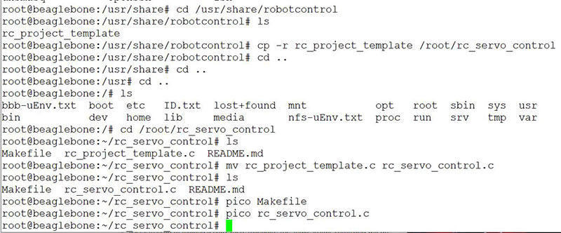
Figure 21. Path to the project template.
Rename the template to “rc_servo_control.c” which is your source file for compiling using “make.” Next, replace the entire body content of the template with that from rc_servo_control.c mentioned above.
After saving in Pico, you can verify the file name. The “c” extension designates it as a source file.
By changing the TARGET in the makefile using the Pico editor (Figure 22), rc_servo_control.c will compile automatically by typing “make.”
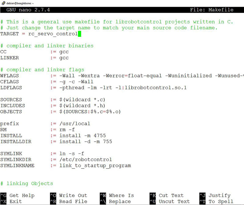
Figure 22. Changing TARGET in makefile.
Remember to save the file by holding the control key and typing the letter “O.” When you’re done, do the same thing with the letter “X.”
Following along in the book, page 79 discusses how to use “make clean” followed by “make” to create the executable file with a lowercase extension “*.o.”
Now you’re ready to run the program and wirelessly control your robot from your computer keyboard!
Hello BeagleBone
We’re at the last step! Type “./rc_servo_control;” without a file extension and you should see the display in Figure 23.
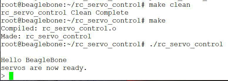
Figure 23. A beautiful sight: Hello Beaglebone.
The first keystroke may not work, but for the next one, type “f” forward, “r” reverse, “l” turn one way, “b” turn the other way, or “q” when you’re done.
Your frameless and wireless differential-drive robot should move around based on your commands. Enjoy! You can change the tire speed(s) by saving your source file then re-compiling.
By harnessing the power of TYT manufacturing and allowing silicone sealant to cure for a day between assembly steps, then bouncing between the book and the website, you can build a simple vehicle that is a first step to something far more complex.
The BBBlue has inputs for many types of distance sensors and quadrature encoders. It has an amazing Inertial Measurement Unit (IMU) that can detect Tait-Bryan angles after it’s calibrated.
Since this robot is a rigid body, the kinematics and kinetics can be explored.
A diff-drive is one of the simplest wheeled robot designs, and the Robot Control Library is one of the most powerful tools a C++ programmer has at his or her disposal.
Where you want to go with this vehicle is all up to you. Start simple and stay calm. I hope this article was helpful! SV
Resources
https://www.packtpub.com/product/beaglebone-robotic-projects-second-edition/9781788293136
http://www.strawsondesign.com/docs/librobotcontrol/index.html
Article Comments