An Experimental Approach to Flipper Geometry
By Troy Mock View In Digital Edition
The Inspiration (T minus seven weeks)
One August afternoon, the words “NEW YORK” and “ROBOT FIGHTING” glimmered across my Facebook feed. It was a post about an Insect combat event in two months, only a four-hour drive from my college town in Upstate New York. Four years had passed since I last peered into a robot arena with a transmitter in hand. However, I had unfinished business.
Designing combat robots had always been an intuitive process for me. Experience and precedence honed my intuition, but I never knew whether my bot’s single tooth disc would withstand the forces of impact.
In the smaller weight classes, bots tend to function longer than expected, often in curious ways. Weapon belts stay on the pulley long after the pulley flange shears; electrical connectors offer structural support when armor has been filleted.
I wanted to push my abilities for this latest build: Create the most powerful Antweight (1 lb) flipper possible.
I wanted to launch opponents as high as possible, potentially up and over the arena wall. I had small-scale pneumatic parts from a previous project.
So, what happens when intuition can only take you so far? Say, when designing the arm geometry of a pneumatic flipper? Unlike relatively simple energy storage formulas for spinners, a pneumatic system is not so easy to quantify. There is the compressible nature of gasses and force equations in which the opponent is not hit but shoved (Figure 1).
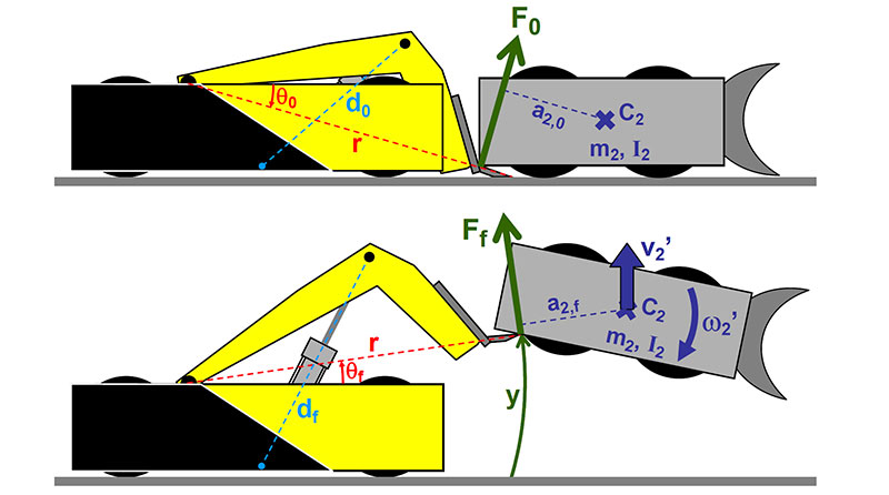
FIGURE 1. From the Riobotz Combat Tutorial — an excellent resource.
I didn’t have the technical know-how to work through the theoretical calculations, so I did the next best thing: Try a bunch of flipper arm designs to see what works best.
Precedents (T minus four weeks)
I first looked at past flippers for clues to focus my experimentation. I collected notes about the arm geometry of Team Inertia Labs’ top machines; notably “Bronco” and “T-Minus” (Figure 2).
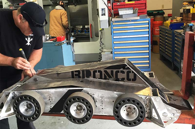
FIGURE 2. Bronco — BattleBots™ heavyweight contender — in the flesh and blood.
While they are in the larger weight classes (60+ lb), their flippers are consistently the most powerful in the sport.
I looked at both the overall design (use of a three-bar geometry) and the small details (like length ratios between the cylinder piston mount and rear pivot arm, and arm tip length).
Through photographs and videos, I mimicked the arm geometry of one of their more documented designs and scaled it down to fit the proportions of an Antweight. From there, I created variations off this base geometry. Modeling in CAD helped me visualize the arm movement across start and end positions (Figure 3).
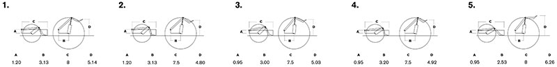
FIGURE 3. Modeling in Rhino 3D.
Once I had created five different arm geometries with differences in angles, lengths, and heights, I laser-cut the arms and support jigs for testing (Figure 4).
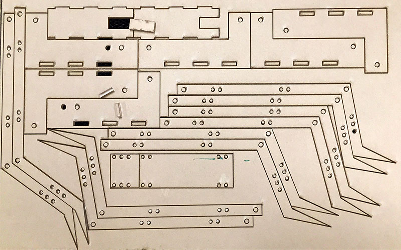
FIGURE 4. Laser-cutting is an absolute time saver.
Testing (T minus two weeks)
When it comes to testing, consistency is key. I mounted my camera on a tripod for a consistent and repeatable frame of reference (Figure 5).
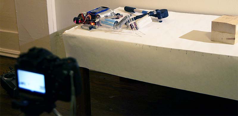
FIGURE 5. Testing jig in my living room.
After filming launches of a wooden test block from all five arm designs, I overlaid the video frames to see the maximum height, number of rotations, and final distance of each wooden block.
From the video frame overlays (Figure 6), flipper arm #2 provided the highest launch and the least spin.
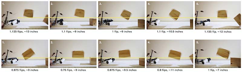
FIGURE 6. No. 2: 4” vertical, 9” horizontal, 400° rotation at 100 psi.
While spin isn’t inherently bad, it diverts energy from the maximum launch height.
I was happy with arm #2, so I fit it to my final design, making slight adjustments such as increasing the tip length to better get under the opponent.
The Build (T minus one week)
However, my end goal was not to figure out the best flipper geometry. It was to create the most powerful Antweight flipper. A local competition (MassDestruction X in New York) served as a perfect real world test with its “plastic Ant” class. Competitors in this 1 lb class were limited to plastic for weapons, armor, and structure. This allowed me to optimize flipper geometry without worrying as much about proper armor against the current breed of vicious Antweight spinners.
With the competition fast approaching, I 3D printed the final arm geometry and constructed the rest of the frame with basic machine tools. I finished wiring the robot together in my friend’s Manhattan apartment the day before. The completed robot came in over an ounce underweight, ready for combat (Figure 7).
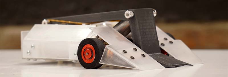
FIGURE 7. Menehune, itching for a brawl at MassDestruction X.
The Competition (T minus zero)
I was welcomed to the overcast skies of Corona, NY with the smell of fresh-made corn tamales outside the train station. I grabbed a few cornhusk-wrapped goodies for the long day ahead.
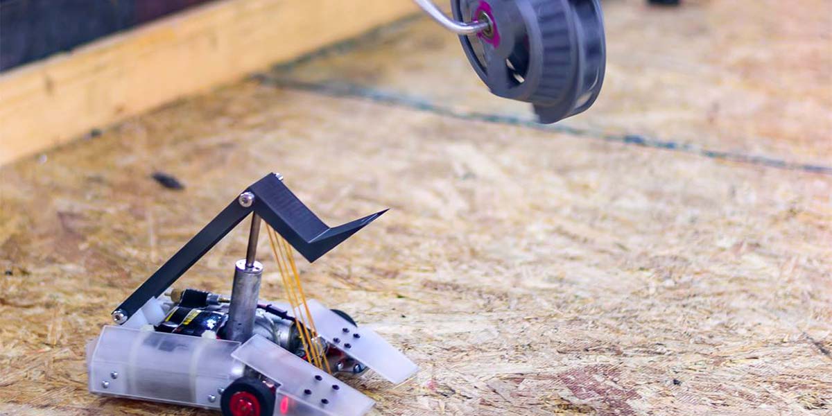
Setup and safety flew by, and before I knew it, Menehune had already fought twice. I was far from bouncing anyone off the ceiling (Figure 8), but I could flip my opponents abreast with relative ease. However, driving ability was made more difficult with a last-minute transmitter issue forcing me to operate the drive controls in an unmixed two-stick arrangement.
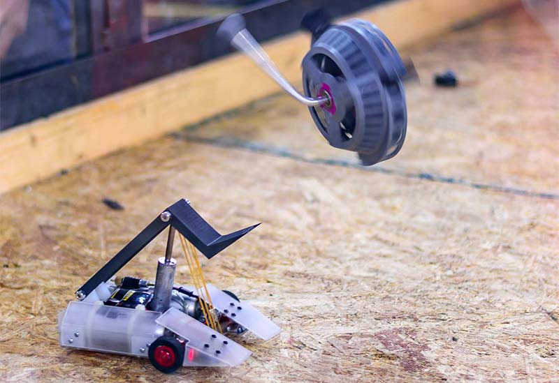
FIGURE 8. Photo credit to Jon C R Bennet.
In my third fight, a viscous overhead spinner bared its ruler-length UHMW bar. I wasn’t impressed by the damage potential of plastic spinners until the lower half of my flipper arm flew into the arena wall. I was wise to bring a spare flipper arm (Figure 9). I fought a few more times, flipping every opponent, but I was thoroughly outdriven in the semifinals.
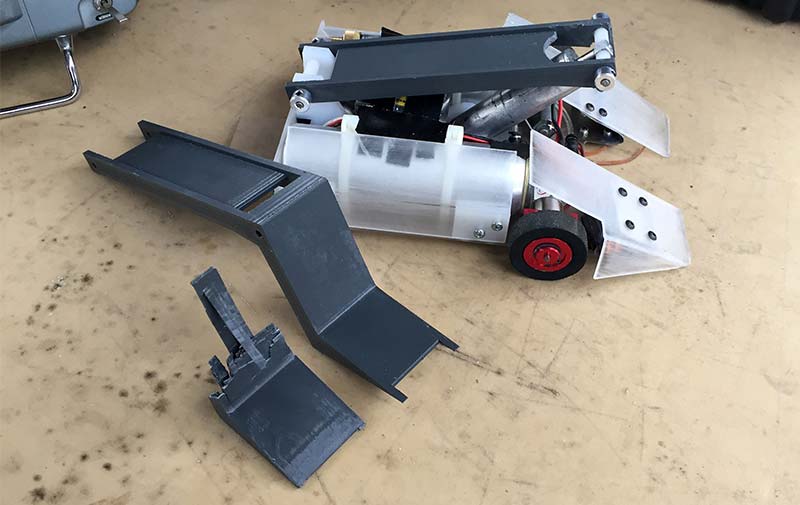
FIGURE 9. Who knew plastic spinners could hit!
Takeaways
To be honest, I was dissatisfied by the performance of the pneumatic system in competition. The flips just were not as high as I expected. I haven’t discussed pneumatic considerations outside of flipper geometry, but for the next iteration, I want to optimize the system for maximum air flow. I have ideas for dual solenoid values and increased port diameters. Additionally, I am not convinced that the three-bar arm geometry is best at the Insect scale. Perhaps a four-bar linkage (Figure 10) will be better optimized for the given cylinder size. Naturally, more testing is in order.
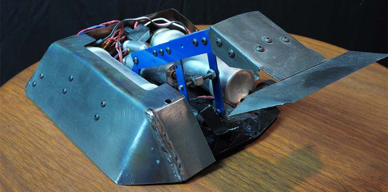
FIGURE 10. Previous design using four-bar linkage.
The beauty of the experimental method is that it doesn’t require a great depth of knowledge for a successful result. All it takes is a fair bit of diligence and a competition to put the experimentation to the true test. A healthy dose of intuition, approximation, and experimentation can take you to great lengths. SV
Article Comments