
An Auto-Targeting Nerf Gun
By Liam Kain, Jonas Funk View In Digital Edition
I’ve always been interested in Nerf guns. They’re harmless and have remarkable range and accuracy. There are many projects centered around making an automatic gun turret, but I wanted to do it with the least amount of materials possible. No camera, no 3D printing; just the materials my partner and I could find lying around in the lab.
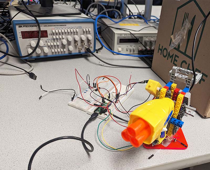
This turret is the least expensive way we could find to create an auto-targeting gun. The turret system shown in Figure 1 works by using a time-of-flight sensor (ToF; distance sensor) to look for targets while spinning on a rotating platform.
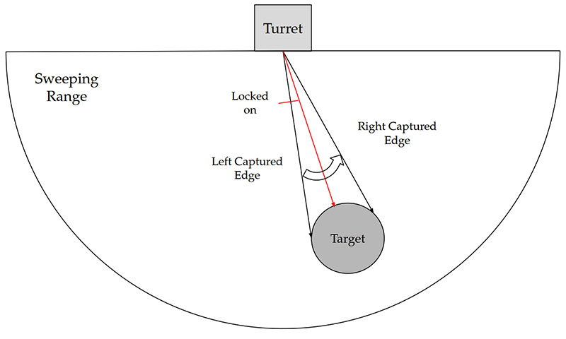
Figure 1: High level diagram.
If an object comes too close, the gun centers in on it and pulls the trigger using a DC motor. This project heavily depends on LEGO Mindstorms parts, so if you don’t have an NXT or EV3 kit, this project may have to be 3D printed or constructed using milled parts instead.
Building
The most difficult part of this project was dealing with the limitations of the hardware. Our build was planned around a Nerf gun pistol I had from my childhood, so the most important piece of the project was already old and inconsistent. We were trying to keep the budget tight, so I expected the same quality from the sensors and motors.
First, we created a rectangular casing to fit around the back of the Nerf gun using LEGO blocks. Then, we created a moving platform for the gun. We found a plastic platform from a storage closet, but a sturdy cardboard box would suffice. Not much torque was required to turn the assembly, so we screwed an inexpensive SG90 servomotor into it and attached the LEGO box. We clamped the platform to a table to ensure the system was balanced. The completed assembly is shown in Figure 2.
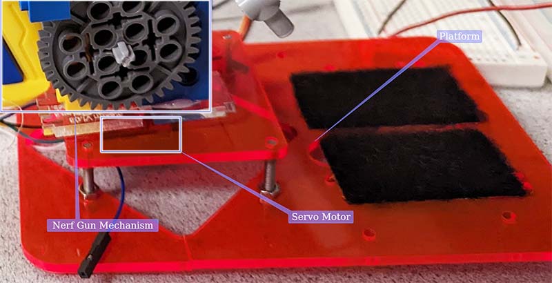
Figure 2: Nerf Gun pedestal.
So, how did we fit the box onto the motor? Usually, a good option would be to hot glue the motor onto the axle or 3D print an adapter, but fortunately, we found an axle adapter (Figure 3) that could fit on our motor.
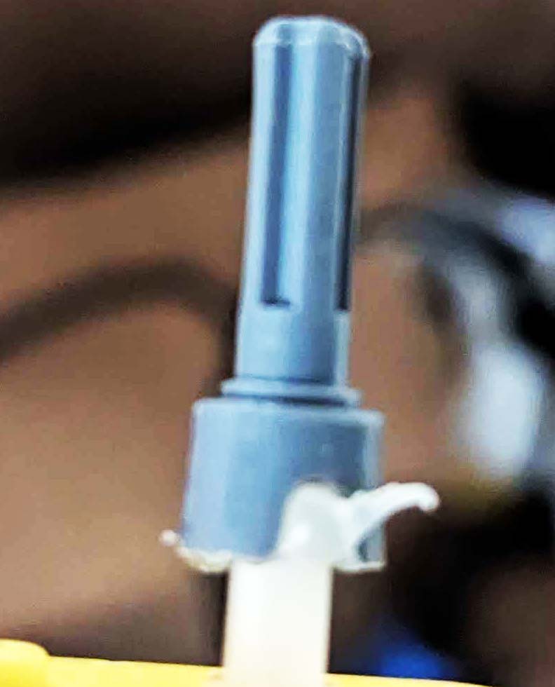
Figure 3: LEGO Mindstorms axle adapter.
We then created a skeleton of Mindstorms parts to accommodate the axle.
Another issue was that Mindstorms parts have different hole spacings than standard LEGO parts, so the bricks used for the box didn’t line up with the Mindstorms connectors. This greatly increased the complexity of the skeleton compared to a box made up of all Mindstorms parts.
With the moving platform done, we had to build a trigger mechanism to shoot the Nerf gun. We found a small DC motor lying around with a plastic axle attached to it. This axle fit perfectly on one of our Mindstorms axle adapters, so this was going to be our trigger motor.
Since this motor was cheap, it had very low torque. Even though we think nothing of pulling the trigger with our fingers, the Nerf gun does have a substantial force requirement to pull its trigger — many times greater than the force that the DC motor could expend. To circumvent this problem, we had to use gear ratios.
If you’re not familiar with gear ratios, then refer to the Resources. As explained in the “Gear Trains” section:
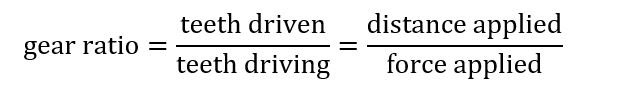
By this logic, if a three-tooth gear drives a nine-tooth gear, then:
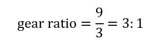
By this equation, every three rotations of the small gear, the large gear makes one rotation. This means the torque required to turn the large gear is split over three rotations of the small gear. Therefore, the torque required to turn the gear train is reduced by 2/3rds.
After trying out different gear ratios to figure out how much force we needed to pull the trigger, we settled on a gear train of 42-, 24-, and 8-tooth gears as shown in Figure 4.
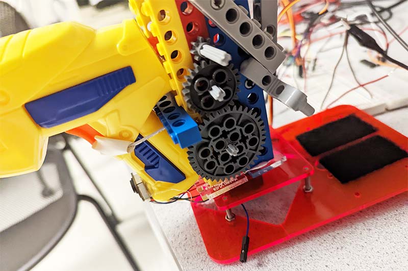
Figure 4: Photo of gear train.
The small eight-tooth gear drove the 24-tooth gear, which drove the 40-tooth gear. In terms of gear ratios, the 24-tooth gear was redundant, so:
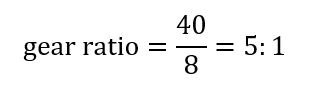
To further increase the gear ratio, Figure 5 shows the addition of another 3:1 gear train.
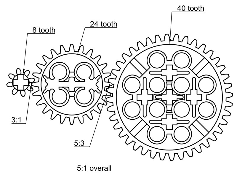
Figure 5: Gear ratio of main gear train.
By connecting the axle of the driven gear to the driving gear of the original gear train, the gear trains chain together, thus multiplying their individual gear ratios.
With this addition, the gear ratio shown on the left side of Figure 6 was:
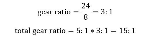
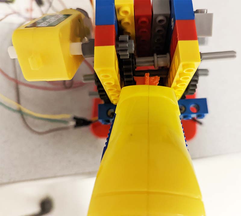
Figure 6: Photo of where motor attaches to gear train.
So, with this gear train (refer to Figure 5 and Figure 7), the DC motor could exert 15 times more pulling force.

Figure 7: CAD model of full gear train.
This force ended up being enough to pull the Nerf gun’s trigger.
With the gear train created, we designed the trigger system by drilling a hole into the Nerf gun. We ran a piece of wire through it, but you could use string or yarn.
We wrapped this around a Mindstorms wheel and attached the end of the gear train to it. We tested out the trigger mechanism, but we ran into a problem.
The gear train exerted force on one side of the axle but not the other side, so the wheel axle was bending from the unequal distribution of turning force. We fixed this by copying the 24- and 40-tooth gears on the other side of the case and connected the two smaller gears with an axle. This way, the wheel would be pulled equally and the axle wouldn’t bend. After this, we tested the motor. It still wasn’t enough power.
Expanding the gear train would do two things: create enormous counterforces on the system and make our system too large to fit on the platform. If you don’t have enough torque, you can always file down the internal trigger mechanism.
Figure 8 shows the Nerf gun trigger mechanism.
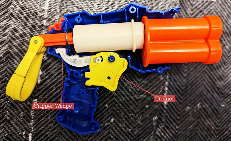
Figure 8: Nerf Gun trigger mechanism.
The trigger wedge holds the orange pillar in a compressed state until the trigger is pulled, causing the wedge to release the orange pillar and fire the gun. Finally, the trigger system worked!
Figures 9 and 10 show the wedge before and after filing the point of contact down, thus reducing the force holding the trigger in place.
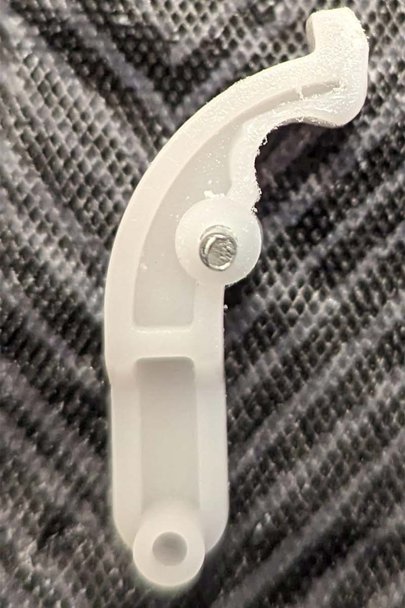
Figure 9: Nerf Gun trigger wedge before filing.
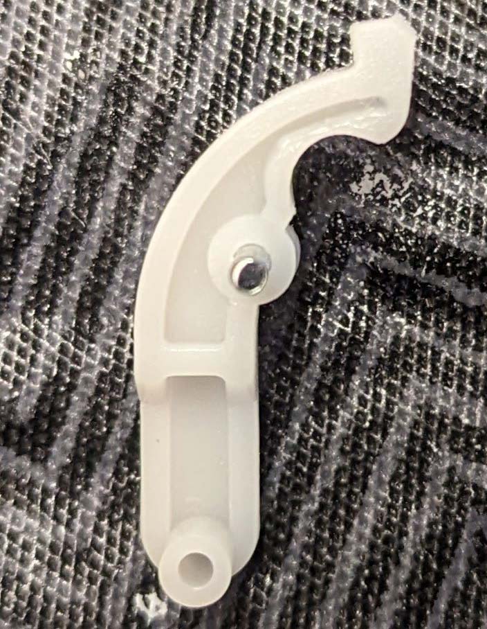
Figure 10: Nerf Gun trigger wedge after filing.
With this modification, the LEGO mechanism could finally pull the Nerf gun trigger.
Most turret projects use an ultrasonic sensor for distance sensing, but we used a TOF1020 sensor as it has a range of about 4m — much larger than the range typical ultrasonic sensors have. The sensor is very small, so we hot glued it onto the front of the Nerf gun.
We had to ensure the sensor faced forward to avoid measuring the ground rather than targets. This can be hard to get right if your gun has a sloped handle, so make sure the sensor faces the desired height.
Electronics
The external electronics we needed were a motor driver, a microcontroller to run the system, and a 3.3V and 7V power supply. Refer to Figure 11 for the hardware diagram.
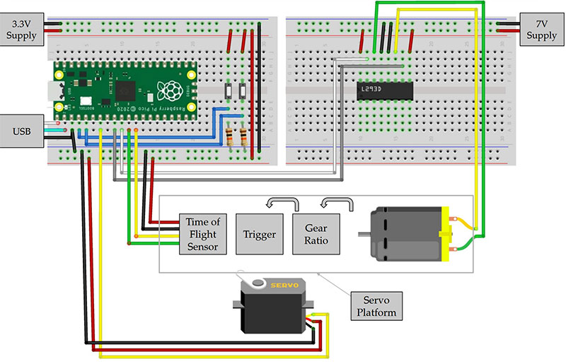
Figure 11: Hardware diagram.
The ToF sensor was arranged according to the pinout listed in Figure 12.
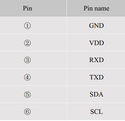
Figure 12: Time-of-Flight sensor pinout (2).
A UART was used, so Rx and Tx were connected to the serial pins on the Raspberry Pi Pico; if I2C were used, then SDA and SCL would be connected.
Next was the motor driver. We used an l297D motor from an electronics kit we had laying around and connected it according to the pinout in Figure 13.
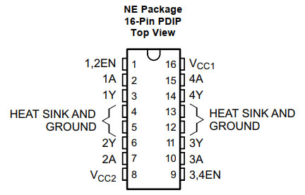
Figure 13: L293D pinout (4).
If you’re not familiar with an H-bridge, it takes in two inputs and produces two outputs. These outputs connect to the positive and negative leads of the motor, so the polarity is up to the designer.
Since motors produce a kickback voltage due to their properties as an inductor, this driver keeps that kickback from going into the power supply or input via an internal snubber diode. We then connected the servomotor according to Figure 14.
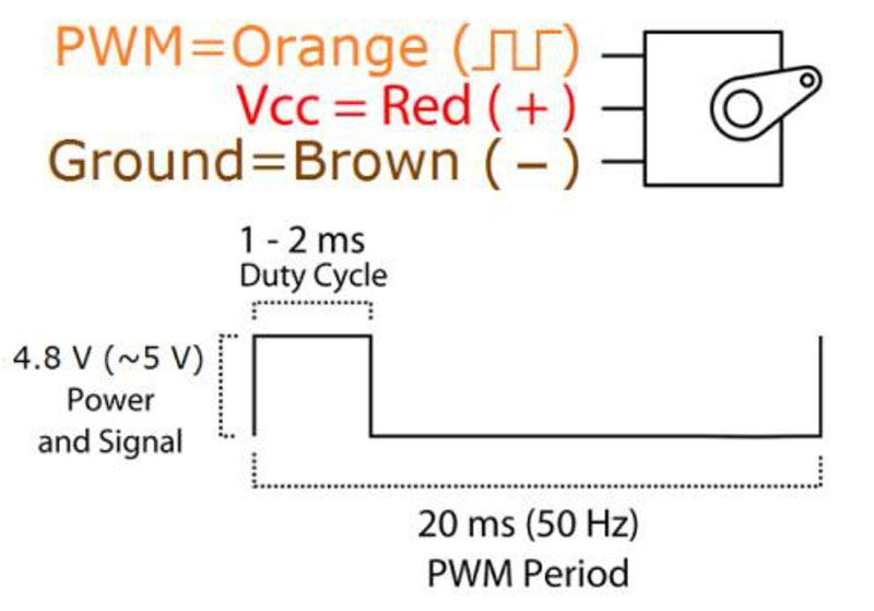
Figure 14: SG90 operation description and pinout (1).
The servomotor only has VCC, GND, and a control pin. With this information, we inserted the components in the arrangement as shown back in Figure 11.
Microcontroller
For the microcontroller, we used an RP2040 processor on the RaspPi Pico development board. It has an easy-to-use software development kit (SDK) and has many useful capabilities compared to using the Arduinos available to us. If you’re unfamiliar with what an SDK is, it’s a library similar to the Arduino framework that allows higher level control of the microcontroller rather than directly manipulating the I/O registers on the RP2040. The RP2040 has various peripherals that we needed to connect the motors and sensor. We planned them out using Figure 15.
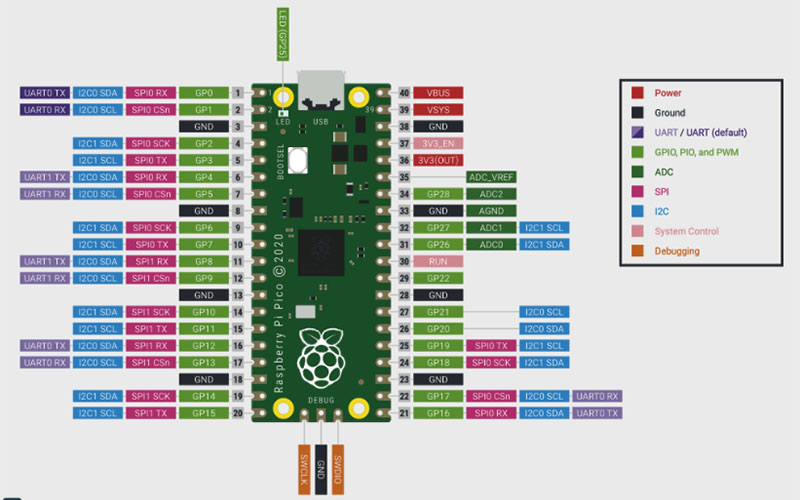
Figure 15: Raspberry Pi Pico pinout (9).
The servomotors (like the SG90) required a PWM (pulse-width modulation) signal to operate and H-bridges do as well, so these inputs could be connected to any free PWM-capable pins according to the Pico pinout. The TOF sensor had both an I2C interface and a UART interface. We chose to connect the Pico to the UART pins as the I2C interface was not working properly.
Software
To run this turret, the RP2040 had to run various processes. It had to read distance data from the TOF1020, rotate the platform servomotor, and run the trigger mechanism motor. To do this, we used the Protothreads library (Resources) which was an easy-to-use threading library, allowing various processes to run in parallel and share variables and other resources between them.
In the first thread, we took sensor data. The ToF sensor was connected via the UART, so we used the UART Pico SDK functions to receive the data. A problem with this approach was that the sensor sent a string like “Range Valid: 15 mm” but sent “Signal Fail” if the sensor got out of range of an object, so a possibly changing expression needed to be parsed for the distance value.
PWM
Before we implemented the second thread, we had to plan out the PWM peripheral. If you’re not familiar with PWM, check the Resources for a good review. According to Figure 14, the input PWM signal must be 50 Hz. To do that on the RP2040, we have to set our PWM period to 1/50 Hz or 0.02s; the RP2040 normally runs at 125 MHz. To do this, we used Pico SDK functions to set the clock divider and wrap value of the PWM module in order to set the PWM period, and thus its frequency.
A clock divider is usually found on a microcontroller’s PWM peripheral that divides the internal clock period of the microcontroller, resulting in a slower frequency for the PWM’s clock. The wrap value (also common to PWM peripherals) represents how many clock cycles the period of the PWM cycle is:
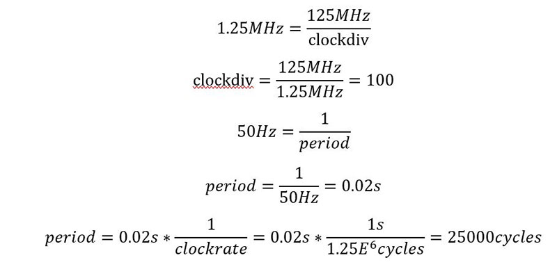
According to these calculations, we used a clock division of 100 and a wrap value of 25000. We chose this pair of values specifically because the Pico SDK maxes the clock division value at 255, so 100 would make calculations easy while also making the wrap value small enough to be a reasonable value.
Finally, we set up an Interrupt Request (IRQ) handler. The IRQ handler in a microcontroller stops any current thread when an interrupt occurs and executes its code, then returns to the thread it jumped from.
Here, we set up an IRQ at the wrap of the PWM cycle, so every cycle, the IRQ handler would run. This allowed the program to make smooth changes to the PWM channels instead of waiting to change these values during execution of one of the threads.
On the RP2040, each PWM channel has two ‘slices.’ so two different pins can be run by the same PWM channel and therefore have the same frequency. Since the DC motor driver had two inputs, those inputs were put on two slices of the same channel. The servomotor input was placed on its own channel.
One problem we encountered was that interrupts were a shared resource between multiple channels, so since there was only one interrupt for wrapping, we could only enable interrupts for one channel out of the two.
We enabled the interrupts for the DC motor PWM channel since this motor benefited most from being modified in the IRQ handler.
Servo
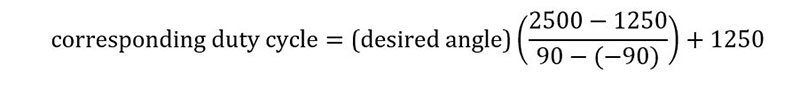
To move the platform in a 180-degree sweep and center the gun onto our object, we needed to be able to set the servomotor to specific angles. To do this, refer to Figure 14 again. The servo operates through a duty cycle of about 1-2 ms (duty cycle is the amount of time during the wave period that is logic high) or about 1250 to 2500 cycles in terms of our program.
We tested these two extreme values on the servo and found it swept over a range of -90 to 90 degrees. To create a function to set the angle of the servo, we simply create a mapping like this:
Sweeping
In the second thread, the meat of the program could finally take place. The thread ran off a state machine described in Figure 16.
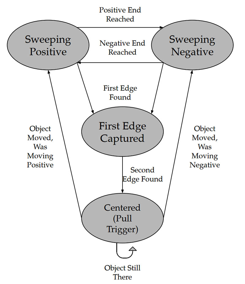
Figure 16: Thread 2 state machine diagram.
While the thread slowly moved the servomotor across a 180-degree sweep, if the distance values read by the first thread started to get closer than a cutoff value (about 2 m), then the thread started waiting to see when this distance spiked in value. By doing this, the program detected both edges of an object.
The program then centered the servo between the two edges it detected and set a Boolean to trigger the DC motor. Remember the IRQ handler? This Boolean got checked in the handler function and set one PWM slice to full duty cycle while the other was left to 0. The motor driver thus saw the forward input as high and the backward input as low; in turn, running the DC motor in the forward direction. After setting this Boolean, the thread waited a few seconds for the gun to shoot and then returned to the starting state, thus repeating the process.
Serial
To help with debugging, a serial output is extremely helpful. The Protothread library (Resources) also has serial_write and serial_read functions that can send and receive data from pt_serial buffers in parallel with other running threads, allowing parallel serial communication while the system is running.
We created a thread with these functions to output the states of the sweep function such as if the first edge had been detected, the second edge, or if the trigger was pulled. We could add other variables during testing if we wished.
Buttons
A final modification was the addition of external buttons to help reload the Nerf gun. The gun had a trigger mechanism, but no way to reload other than manually, so adding buttons to relax the tension on the trigger made reloading much easier.
To do this, we used the GPIO SDK functions to connect external buttons to the pins of the RP2040 as seen back in Figure 11. We could then check the state of these buttons in the PWM IRQ handler and move the motor in both forward and reverse direction.
Finished Product
With the components wired up and the program completed, the gun was able to successfully aim at an object up to 2m away in 5 to 10 seconds. Because the ToF sensor can’t differentiate between different objects, the gun had to operate in an open space or else it would shoot at a chair or table. However, inside of that open space, it was very effective at zeroing in on an object in front of it. We tried to speed up the rate at which the gun rotated, but it started to get very inaccurate as the delay of the time-of-flight sensor became too great to update the system in time.
To pull the trigger, we had to run the DC motor at a voltage of about 7V, but even with that voltage, our H-bridge posed a problem. Unless one of the outputs was tied to ground, the driver would not output at full power and the motor would not be able to pull the trigger.
The finished project.
One issue that may have caused this is that the L293D is a four-set of half H-drivers, not a set of full H-bridges, so the outputs we were measuring were independent of each other. Using a full H-bridge may get rid of this problem, or simply using a higher torque motor.
In hindsight, the gun would have been much more stable, effective, and nicer looking if we had used resources like 3D printing and cameras, but we think the simplistic nature of the turret gives it its charm. It can be built with pieces that are just laying around, with the only store bought piece being a ToF sensor which could possibly be replaced with an ultrasonic sensor. All in all, for its cost of materials and tools, the turret proved a success. SV
Parts List
Motors
1x DC Motor (most small DC motors will do)
1x S90 Servomotor
1x l293D H-bridge
Sensors
1x TOF10120
LEGO Mindstorms Pieces (found in a standard NXT robot set)
1x 5x11 Module
3x Large Axle
1x Small Axle
2x Angular Connector
10x Bushing
10x Standard LEGO Bricks
1x Wheel
2x Axle Adapters (may not be present)
2x Eight-tooth Gear
3x 24-tooth Gear
2x 40-tooth Gear
Cables
10x Male-to-Male Jumper Wires
6x Female-to-Male Jumper Wires
Miscellaneous
Cardboard
String
Resources
Completed Project with Jonas Funk
Web Page: https://ece4760.github.io/Projects/Fall2022/ljk74_jwf224/index.html
Source Code: https://github.coecis.cornell.edu/ljk74/4760-final
Project Video: https://youtu.be/sDSVvzvK2oA
http://www.ee.ic.ac.uk/pcheung/teaching/DE1_EE/stores/sg90_datasheet.pdf (servo motor datasheet)
https://www.electroniclinic.com/wp-content/uploads/2021/06/TOF10120-Datasheet.pdf (Time of Flight Sensor datasheet)
https://cdn.sparkfun.com/datasheets/Sensors/Proximity/HCSR04.pdf (Ultrasonic Sensor datasheet)
https://www.ti.com/lit/gpn/l293d (H-bridge datasheet)
Gear Ratios Overview: https://science.howstuffworks.com/transport/engines-equipment/gear-ratio.htm (gear ratio explanation)
Protothreads Overview: https://people.ece.cornell.edu/land/courses/ece4760/RP2040/C_SDK_protothreads/index_Protothreads.html
PWM Overview: https://microcontrollerslab.com/pwm-introduction-types/
Raspberry Pi Pico Datasheet: https://datasheets.raspberrypi.com/pico/pico-datasheet.pdf
Raspberry Pi Pico SDK Datasheet: https://datasheets.raspberrypi.com/pico/raspberry-pi-pico-c-sdk.pdf
Iteration I Wanted to Simplify: https://youtu.be/S3CwzkT6cK4
Article Comments