
Alpha-Writer: A Computer-Controlled Letter Writing Robotic Arm
By V S Rajashekhar View In Digital Edition
Back from my school days, I remember my teachers giving homework that involved a lot of writing. I always wondered why there couldn’t be a robot that would do this task of writing homework for me. I’m glad it’s now possible to make this happen.
As I moved forward to do my Masters in Advanced Manufacturing, I had a course on industrial robotics. While doing that class, our professor came up with an idea that a simple two-link robot could be used to write letters. Figure 1 shows the simple two-link robotic arm.
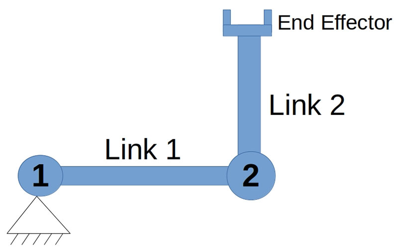
FIGURE 1: Representation of a simple two-link robotic arm with joints and end effector.
It’s called a 2R robotic arm since it has two revolute joints connecting two links. At the end of the robot, there’s an end effector which, in our case, is a pen to write the letters.
In this DIY project, I’ll show you how to make a simple computer-controlled letter writing robot from scratch. Once you have all the required materials, it will take about an hour to complete the build. The robot arm writes a designated letter on a piece of paper when a particular button is pressed on the screen that’s part of the build. You can see what it’s writing in the camera using the Graphical User Interface (GUI).
You can see the robot arm in action at https://youtu.be/-GWMAvIMX4w.
Make Sure You Have These to Begin
First, we’ll be making the two-link robotic arm. For this, we’ll need two servomotors with at least 10-15 kg cm torque for better results. You can also use 9g servo motors.
Next, is two 30 centimeter wooden or steel rulers to make the links of the robotic arm.
Try changing the initial angle of the mechanical robotic arms and you’ll find differences in the font style!
A drill and a few nuts and bolts are necessary to fit the wooden or steel ruler to the servo horn. An L clamp or a piece of sheet metal that can be bent into an “L” shape is needed to hold the pen or pencil using a paper clip.
A few male-to male jumper wires are needed to connect the servomotors to the microcontroller. An Arduino Uno with a USB-UART cable is the microcontroller I used. A 5V 1A power supply is required to power the servomotor.
Building the Two-Link Robotic Arm
Find a big pad or a table and fix one of the servomotors to it. Attach the ruler to the servo horn using the nuts and bolts. Attach the second servomotor to the other end of the ruler. Your setup should look something like Figure 1. You’ll now need to make a similar horn and ruler setup as shown in Figure 2.
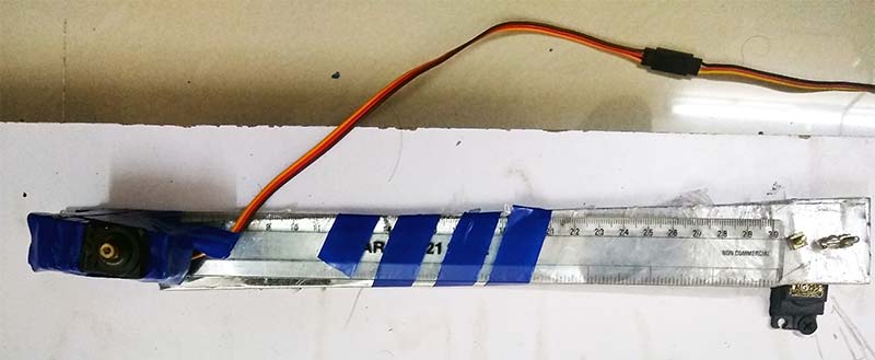
FIGURE 2: The first servomotor is attached to ground. The ruler is connected to the horn. The second servomotor is attached to the other end.
Next, attach the L clamp to the end of the ruler so that the pen or pencil can be attached to it. Refer to Figure 3.
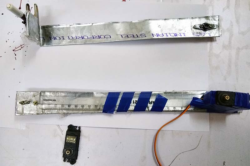
FIGURE 3: The second link of the robotic arm is made by attaching to the horn of servomotor 2.
Attach the servo horn with the ruler and pen to the second servomotor. Your two-link robotic arm is ready and should resemble Figure 4.
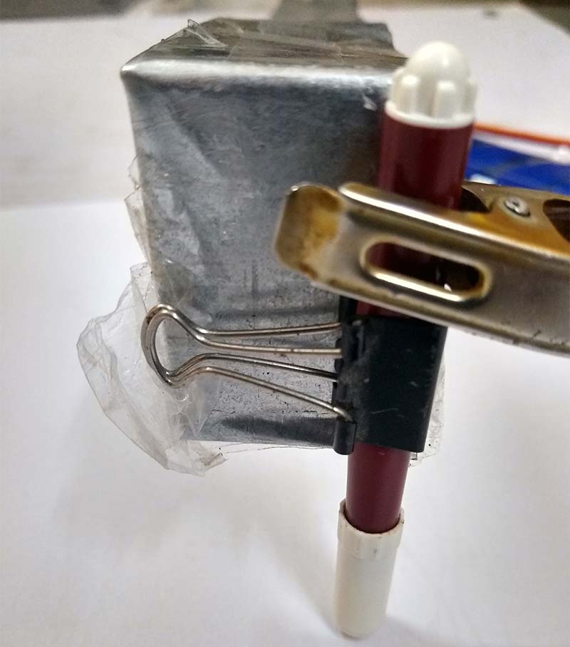
FIGURE 4: The color pen attached to the L clamp made of sheet metal. This is the end effector.
Circuit Connections
The circuit is shown in Figure 5.
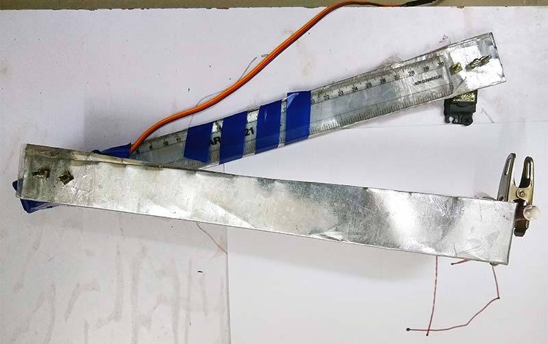
FIGURE 5: The assembled robotic arm ready to write the letters.
A breadboard is used and the 5V 1A power is attached to it. From this, the power is distributed to the two servomotors. Pins 10 and 9 are given to the servomotor as 1 and 2, respectively.
Here, servomotor 1 is the grounded motor and servomotor 2 is the motor that is attached to the link connected to servomotor 1.
Finally, connect the male-to-male jumper wire from the ground pin of the Uno to the ground in the breadboard.
Software Setup and Running the Code
A. Programming the Microcontroller
Open your computer and install the Arduino software. You can get it from https://www.arduino.cc/en/Main/Software.
Open the Arduino file that is included with the downloads for this article. Connect the Uno to the computer and upload the code. Remember to keep the board connected to the computer until the end of the project.
The following block of code tells you that the letter A will be written if the button A is pressed in the GUI (covered next):
if(val == ‘a’){ //if a received
myservo1.write(0);
myservo2.write(15);
delay(2000);
.
.
.
myservo1.write(0);
myservo2.write(22.5);
delay(2000);
}
If button A is pressed, that value is sent to the microcontroller. It makes servomotor 1 (myservo1) and servomotor 2 (myservo2) move to certain angles with a delay of two seconds in between each transition.
The more rigid the robot is, the more accurate the letters written will be!
B. Graphical User Interface
- Download the Processing software at https://processing.org/download.
- Open the file alpha_writer.pde that’s in the article downloads.
- Look out for this line: port = new Serial(this, “/dev/ttyACM0”, 9600);
Replace “/dev/ttyACM0” with the port name to which your Arduino is connected. Don’t forget to use the double quotes. - Run the Processing program and you should get the screen shown in Figure 6.
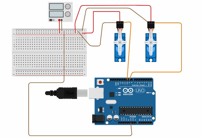
FIGURE 6: The circuit diagram of the robotic arm with the motors and microcontroller.
Success! You’re ready to write letters by clicking on the button shown in the screen.
Adjust a camera (possibly a web camera) over the robot so that you can see what it’s writing.
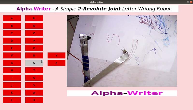
FIGURE 7: A GUI used for giving the input to the robotic arm.
Watch the computer-controlled robotic arm writing all 26 English letters at https://youtu.be/0612D6gnf3U. By adjusting the initial position of the links, the robotic arm writes in a different font as shown at https://youtu.be/5QB-lQINRKw.
I hope you find this “write” on the money for your next computer-controlled project! SV
Article Comments