
Adventures in Laser Center Finding — Part 2
By Edward Andrews View In Digital Edition
Last time, I presented a way to mount a couple of lasers to a milling machine or drill press to project some laser lines down onto the machine bed so that you can see exactly where the drill or mill cutting tool will land. This is a necessary step whether you are drilling a single hole or trying to set a home starting point for a CNC machine.
This time, we’ll go a little farther and discuss another scheme of laser assisted center finding.
Spindle-Mounted Laser Center Finders
During my web research of how lasers can be used in center finding applications, I discovered a good looking commercial laser centering device from SDA Manufacturing located in Piedra, CA (www.lasercenteredgefinder.com). As depicted in Figure 1, this device has a small laser in-line to a shaft that is held in place in the drill press chuck/milling machine collet.
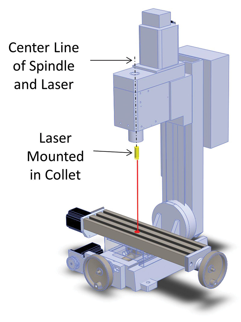
Figure 1. Spindle mounted laser scheme.
Since the mill/drill spindle is NOT TURNING while in use, the device can be battery or AC powered through an umbilical cord.
With this method, the laser is turned on and a red dot is projected precisely down the center line of the spindle, landing on the work surface exactly where the center of a cutting tool will be. The operator simply moves the X-Y table until the laser dot hits the desired target point on the work piece, registers the location in the machine software, and voilà! You’re off and running!
Several models are offered by SDA, one of which is small enough for use with smaller scale drill presses and mini-mills. All units appear well built and are priced in the $125-$150 range. A recent visit to their website revealed that each unit comes with several lenses — one of which appears to project a centering dot within a series of concentric circles. I’m impressed with the SDA product and suggest that it is a viable solution to anyone in need of a quick, ready-to-run, off-the-shelf solution.
As with any laser approach, perpendicularity to the stage is essential for good results. Furthermore, alignment to the spindle center line is also required. At first, this would seem simple as the laser module itself has a tubular case and everything sort of looks like it will be concentric.
However, the centering and perpendicularity of the laser diode within its case may not be well controlled. Thus, the challenge begins. While this issue seems solvable, some imagination and tinkering will be needed to achieve successful alignment. For myself, I opted not to “reinvent this wheel.”
Rotating Spindle Laser Center Finder
Another centering idea I found was well demonstrated in a YouTube video called “Making Prototypes” by Dan Gelbart. Part 15 of his series (https://www.youtube.com/watch?v=otSjut1iGGk) showed (among other things) how milling machine work-piece center finding can be achieved using a rotating laser device. This is different from the spindle laser method previously described in that here, the laser is mounted at a slight angle from vertical and offset from the axis of the spindle. Also, with this approach, the spindle is turning while using this laser centering device!
The rotating spindle laser center finder is depicted in Figure 2.
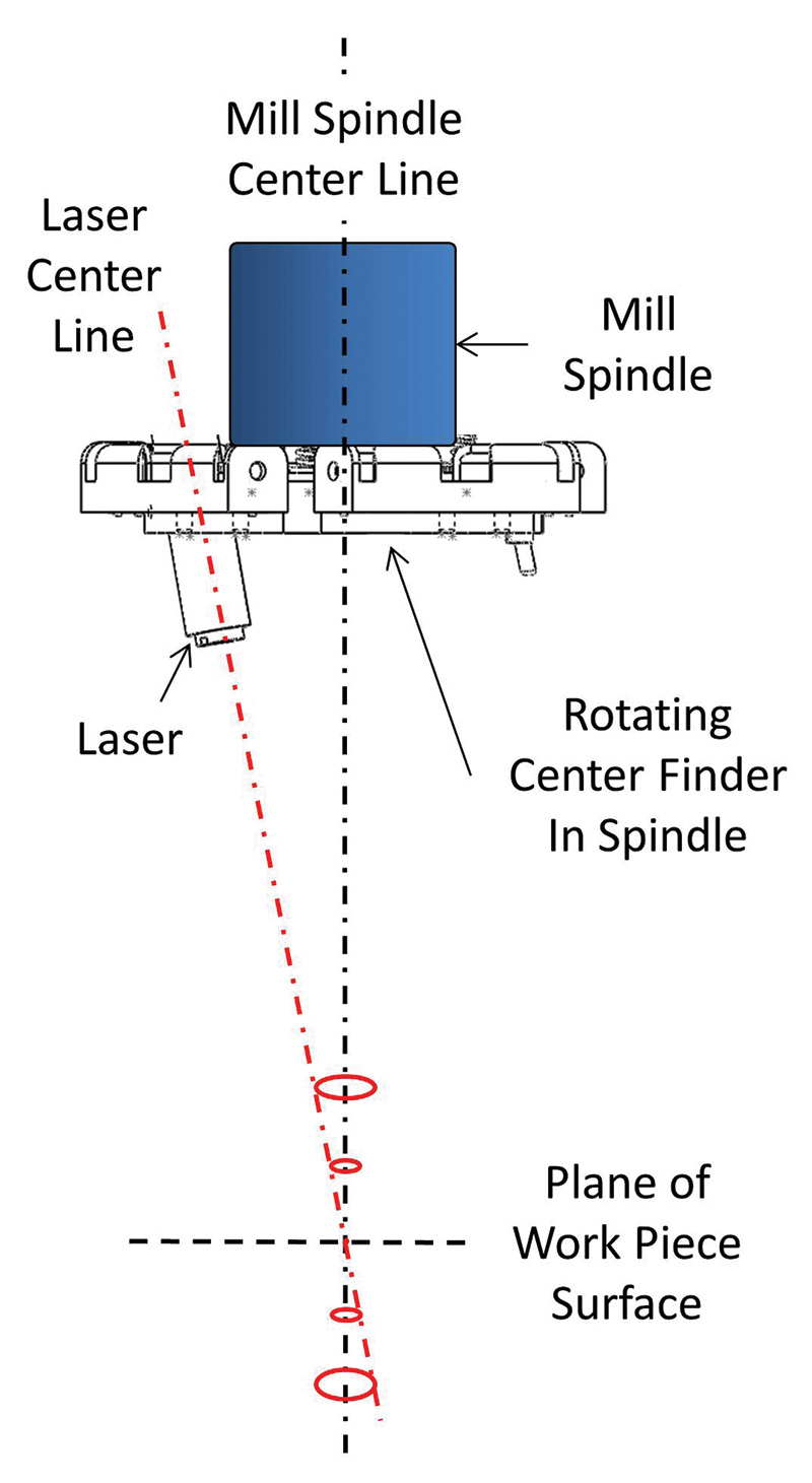
Figure 2. Basic geometry of a rotating laser alignment design.
As shown, this rotating laser device actually traces a circle onto the surface of the workpiece. By changing the height of the Z axis, the diameter of the laser circle grows larger or smaller. At exactly one Z axis height, the laser beam converges to a single point marking the exact center of the machine tool bit.
In his video, Dan showed how easy it is to use a device like this to center the machine on any fixed spot or circular work piece feature. He also showed how this approach can be used to easily find the precise center of any rectilinear feature of the work piece. These are very handy attributes that are only possible with this rotating laser scheme.
Nigel Taylor is another individual who has reduced this to practice and produced a video of his accomplishments (https://www.youtube.com/watch?v=q_aa4rANib0).
This scheme seemed way cool to me and gave me the itch to give it a try.
Rotating Center Finder Device Geometry
Since I couldn’t find any “fabrication-ready” part documentation, I proceeded to lay out and model my own version using my SOLIDWORKS CAD program. Since I used SOLIDWORKS professionally, I was able to leverage this tool to develop this device.
For other designers, there are many low cost/zero cost 2D and 3D software packages you might consider. However, this project is simple enough that a calculator and the back of an envelope can suffice.
Figure 3 shows the device geometry.
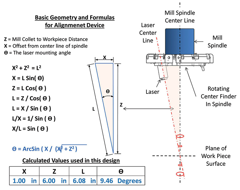
Figure 3. The geometry and math behind this device. I used the formula in blue to calculate the mounting angle for the laser.
The formulas that define the sides and angles within a right triangle are used to define relationships and calculate the key values.
To provide mechanical clearance between the laser body and the spindle body, the laser offset radius, “X,” needs to be at least the mill Spindle _Radius + Laser_Body_Radius. Since the diameter of my spindle is 38 mm (~1.5 in), its radius is about .75 inches. The diameter of the laser body is about .5 in, making its radius about .25 in. Therefore, I set X to be 1.0 in.
The Z dimension is the distance from the mill collet to the X-Y table where the laser circle size = 0. This dimension is high-side limited by the total vertical spindle travel of the mill plus the thickness of the material you’re working on. It’s low-side limited by the minimum laser focus distance. I measured the minimum focus distance for the laser to be about 2.5 inches, so this isn’t a major design driver.
Lastly, don’t forget to consider that you will want to provide some reserve above and below the Z distance, so you can project circles of differing sizes at different Z elevations. Considering all of these points, I set Z = 6.00 inches for my machine setup.
Plugging in X = 1.0 and Z = 6.0 values, the equation showed me the calculated laser angle, q, to be 9.5 degrees; I rounded up to 10 degrees.
You can change these numbers to suit your machine needs and crunch the formula using a hand calculator. It isn’t hard to whip up a quick spreadsheet to do the math, so you can readily model several geometric combinations.
Making the Rotating Center Finder
Only two custom parts and a handful of common hardware are needed to build the rotating center finder.
The main LASER_PLATE (Figure 4) is a 2.8 inch diameter disk made from .125 thick aluminum sheet metal.
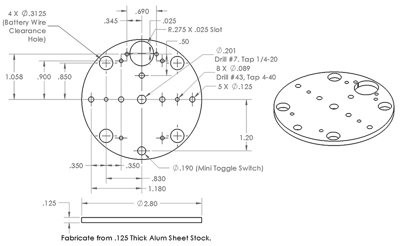
Figure 4. Main LASER_PLATE.
This plate becomes the core to which all else is attached. A 1/4-20 x 1 inch long machine screw goes through a tapped hole in the center of this plate and becomes the shaft that is placed into the drill press chuck/milling machine collet during use.
I was able to set up my CNC mill to make this part, but a 1X printout of the part drawing can be readily used to transfer (punch) the holes and reference marks onto blank sheet metal stock. Drilling a few holes followed by tapping the eight 4-40 and one 1/4-20 threaded holes finishes the part. Take note that due to the 10 degree angle of the laser, the hole in the plate that the laser body goes through is elongated. A coarse file can be used to enlarge a normal drilled hole as needed.
The second custom part is the LASER_COLLAR. The LASER_COLLAR (see Figure 5) grips the laser and is attached to the LASER_PLATE using three spring-loaded screws. This creates a ‘three-point floating mount’ for the laser.
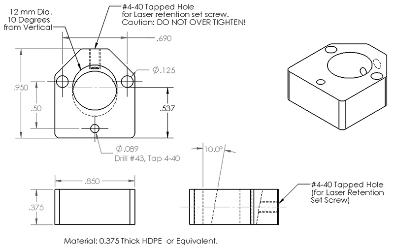
Figure 5. LASER_COLLAR.
This floating mount approach provides for easy laser adjustment, using just two of the three spring-loaded screws. With these screws, one can easily align the laser beam and compensate for any laser, lens, fabrication, or tolerance stack-up errors.
I frequently mill out first time parts in plastic as it’s easier to machine and more forgiving to my mill bits if I make a mistake in the G-code. To this end, I made the LASER_COLLAR from .375 thick HDPE (high density polyethylene) plastic sheet that I had on hand thinking I would make the “final part” from aluminum stock.
However, I found the plastic part worked just fine as-is. Feel free to substitute aluminum or almost any other strong plastic for the part. Just bear in mind that the LASER_COLLAR must endure the centripetal load of the mass of the laser during spindle rotation. As such, don’t use brittle or weak materials for this part as you don’t want it to break or shatter while the device is rotating!
The laser mounting hole in the LASER_COLLAR must be drilled at a 10 degree angle from vertical. To perform this operation, I clamped the part in a small mill vise and then stuffed shim blocks under one side of it until I had the vise (and part) tilted 10 degrees. I then used clamps to secure the vise to the drill/mill table so it would remain stable throughout the drilling process.
The total height of the shim blocks needed depends on the size of the vise. You can use a protractor or calculate the shim height using the Figure 3 formulas. Of course, if you own a “high-tech” tiltable vise, you have an even easier solution!
Rotating Center Finder Assembly
The complete Parts List for the rotating center finder is found in Figure 6.
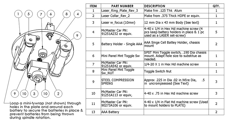
Figure 6. Assembly guide and parts list.
The laser is a small 12 mm Die x 36 mm long module that I bought from eBay vendor asab.design. These units were spec’d for 5 mw of output power and were priced at three for $12. There seem to be many sources that offer compatible parts. Just be sure the unit you buy is FOCUSABLE, has a DOT OUTPUT, and will run off of 3 VDC.
There is nothing particularly special about the battery holders. I decided to use two single cell holders as opposed to a two-cell unit as I wanted to distribute the battery mass in a balanced way.
Figure 7 details the assembly of the three-point laser mount.
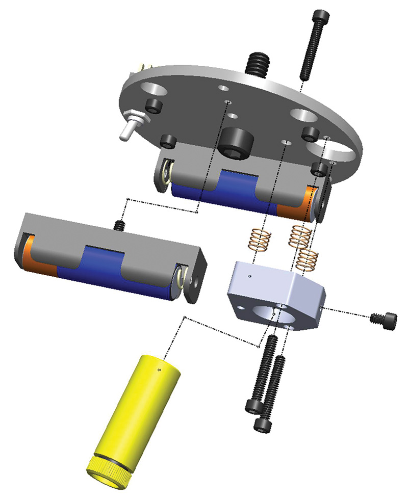
Figure 7. Assembly guide for the LASER_COLLAR.
Almost any compression spring should work. I started looking for something akin to a ball point pen spring, but before I could find some pens to cannibalize, I checked a “bag-o-springs” assortment that I had in my shop. I found some small springs that were about .2 in ID and approximately 1/2 inch long (uncompressed) that worked well.
If you can’t find a suitable spring in your junk box or at a local hardware store, McMaster-Carr is a source to consider. The rest of the hardware is garden variety machine screws.
Figure 8 shows a top view of the completed assembly (wires not shown). The protruding 1/4-20 machine screw is the shaft that goes into in the drill press chuck/milling machine collet.
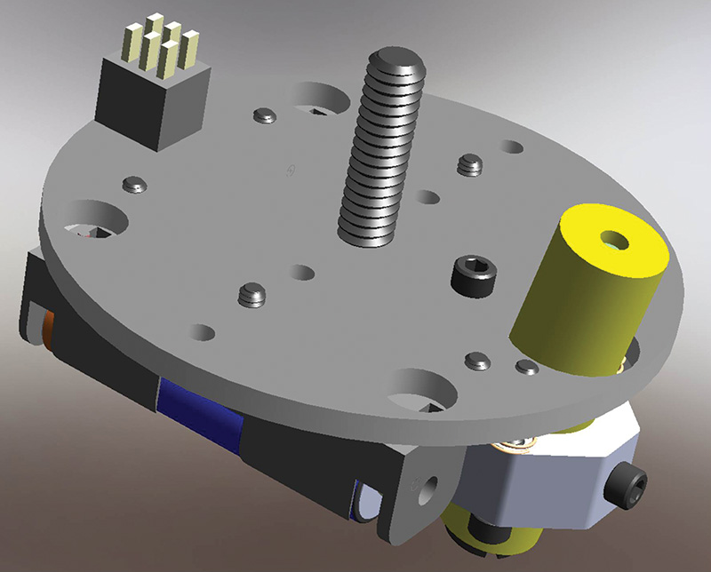
Figure 8. Top view of completed assembly.
Figure 9 is a bottom view of the assembly. BE SURE TO ADD TIE WRAPS TO KEEP THE BATTERIES IN PLACE! The two hex head 4-40 screws in the LASER-COLLAR are used to align the laser.
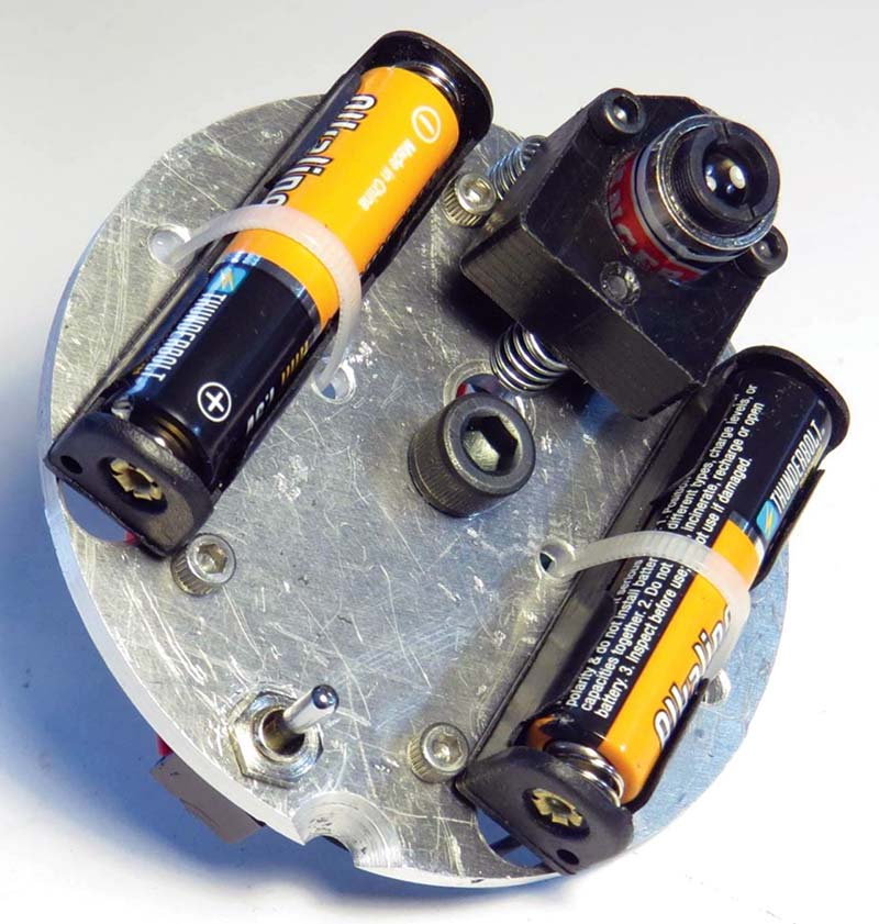
Figure 9. Bottom view of finished assembly. Tie wraps are required to hold batteries in place.
Wiring
This alignment device is powered by a pair of AAA batteries. The batteries are symmetrically mounted to the LASER_PLATE to keep the whole assembly reasonably well balanced. The power switch is a miniature toggle variety that is mounted through the LASER_PLATE. The battery holder wires are routed through the LASER_PLATE wire access holes, and then the holders attach to the plate using 4-40 flat head or button head screws.
Refer to the schematic and wire routing diagram shown in Figure 10 to complete the wiring.
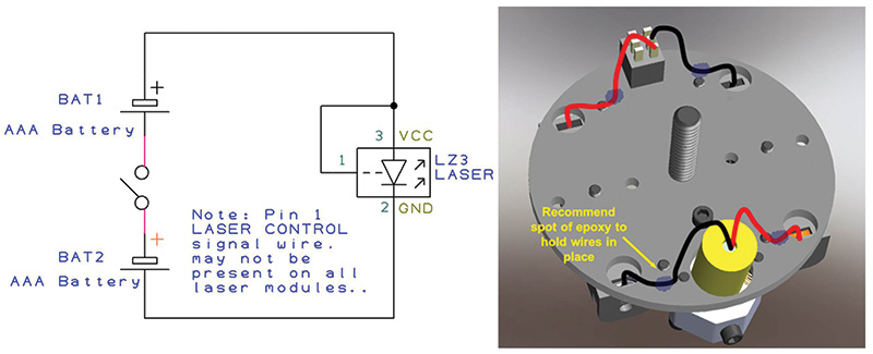
Figure 10. Alignment device schematic and wiring.
Use minimal wire lengths and heat shrink tubing to protect all splices. I also suggest that you consider using some spots of glue (epoxy or equivalent) to secure the wiring to the LASER_PLATE as this will reduce the stress on the wires due to centripetal force. The simple lasers that I used had just two power supply wires with black = GND and red (usually) = +VDC.

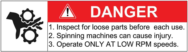
Rotating Center Finder and Machine Safety
As you’d expect, safety glasses and other machine shop safety rules apply when the rotating alignment device is mounted and running in your machinery. I would add the recommendation that the rotating center finder device be carefully inspected prior to each use.
Also, be sure the battery cable ties are in place and that there are no loose screws or other parts that could fly off the device as it rotates. I added cable ties around the battery holders after seeing a battery loosen up and become a flying projectile! Don’t let this happen to you!
Along these same lines, I strongly recommend that the rotating alignment device only be used in variable speed machines, and then only at speeds less than 1,000 RPM. Do not use in DRILL PRESSES or ROUTERS if slow speed start-up and low speed operation is not available.
Laser Safety
Even the relatively low power 5 mw RED laser used in this project is able to produce extremely bright, tightly focused, high energy beams of light. Such light can damage your vision!
DO NOT STARE DIRECTLY INTO THE LASER BEAM AT ANY TIME!!
Also note that the basic geometry of the rotating alignment device can result in VERY BRIGHT reflections of light. This is especially evident when the laser circle is small or has converged to a single point. Use caution when laser centering on highly polished or reflective surfaces as the reflected light can be very intense!
Rotating Alignment and Setup
Rotating center finder alignment and setup is easy. Here are the steps:
Initial Setup (Steps 1-7) and Final Adjustment/Alignment (Steps 8-14)
- Inspect the device to be sure all of the hardware is tightened. Make sure the battery tie wraps are in place.
- Start by setting all alignment adjusting screws so that the three-point LASER_COLLAR is spaced about 1/4 inch from the surface of the LASER_PLATE. Turn each of the three spring-loaded screws until the COLLAR is visually parallel with the LASER_PLATE.
- Unthread and remove the focus lens mount from the laser. Place a wrap of plumber’s Teflon tape around the threads and reassemble. Check the laser lens to be sure that it’s threaded into the laser far enough so as not to be loose, ‘wobbly,’ or prone to come out. Don’t worry about focus yet; this will be checked and set later.
- Mount the alignment device into the machine collet and turn the laser on. You will see the laser dot on the stage of the mill. As you manually turn the spindle, you’ll see a circular path traced out on the work surface.
- With SAFETY GLASS ON, turn on and slowly ramp up the spindle speed. You’ll see the rotating dot become a circle. Keep the RPMs low until you are confident that nothing is loose or severely out of balance.
- Now begin moving just the Z axis of your mill/drill. You should see the diameter of the circle grow and shrink as you move the Z axis up and down. While the circle size will vary, it will probably not shrink to a single point just yet.
- Move the Z axis until the circle is as small as it can get. Stop the spindle rotation. With the initial setup completed, fine adjustment is now possible. I found that placing and targeting a 1/4 in ID washer on the machine X-Y table is a useful assist for making the following fine adjustments.
- STOP THE SPINDLE ROTATION.
- Now, turn each of the two adjustment screws accessible from the bottom of the alignment device while it’s still in the mill. By turning these two adjustment screws, the dot will move.
- Using the adjusting screws, move the dot as close as you can to the center of the washer target.
- Manually turn the spindle and observe the motion of the dot; stop periodically to try slightly different centering screw adjustments.
- At this point, you can also focus the beam by rotating the laser FOCUS RING until the spot is as small and well-focused as possible.
- SLOWLY ramp up the spindle speed; you’ll probably see a circle that is smaller and better focused that you had previously achieved.
- Move the Z axis until you find the smallest circle possible and repeat steps 8-13. You are done when you see a single stationary dot.
Once adjustment is complete, you can apply some Loctite to the adjusting screws if needed to help hold the adjustments in place.
At this point, it should be possible to put the device into and out of your machine without need for realignment. However, a drop or jar of the assembly can throw things off.
A Few Diagnostics
One of the intrinsic things about this spindle mounted design is that even when the device is in need of some fine-tuning, it remains accurate and useful as long as the feature you are targeting is larger than the smallest circle spot you can trace. Here are some diagnostic tips to optimize your build:
- If you find that the laser circle no longer converges onto a single point through Z axis movement, realignment is indicated.
- If you find the unit doesn’t seem to hold alignment well, equally tighten all three LASER_COLLAR mounting screws to increase the overall spring tension on the three-point laser mount. Then, realign the unit and try again. Alternately, you can install stronger springs to increase the stability and rigidity of the three-point mount.
- Focus fine-tuning is indicated if you observe a large dot diameter or thick laser circles.
Summary
In this series, two different laser center finder designs have been presented. The availability of small low-cost lasers makes projects like this easy and fun to construct.
While I came into this challenge expecting to make just one device, I ended up building two different tools. Each approach provides its own features and benefits, and as shown in Figure 11, I sometimes end up using both gizmos at the same time!
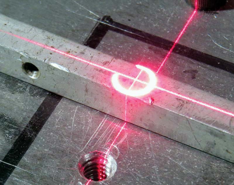
Figure 11. Centering on the middle of a 1/4 inch square bar stock.
These alignment tools have improved the speed and accuracy of my machine setups. I hope you also find these ideas useful and can spring-board and improve upon these designs to fit your specific needs and applications.
Although I’ve focused on my mini-mill needs, these concepts will work for any drill press or milling machine. The fixed spindle mount design should also work well with CNC routers.
I encourage you to spring-board off of these designs and adapt and optimize laser centering for use in your machine shop! Happy machining! SV
eBay Link to Laser Pointers:
https://www.ebay.com/sch/i.html?_from=R40&_trksid=p2334524.m570.l1313&_nkw=laser+pointer&_sacat=0&LH_TitleDesc=0&_odkw=saab+design+laser+pointer&_osacat=0
YouTube Video "Building Prototypes, part 15 of 18, Mill and Lathe" by Dan Gelbart:
https://www.youtube.com/watch?v=otSjut1iGGk
YouTube Video "Laser Alignment Tool" by Nigel Taylor:
https://www.youtube.com/watch?v=q_aa4rANib0
Article Comments