
Adventures in Laser Center Finding — Part 1
By Edward Andrews View In Digital Edition
Semi-autonomous vehicles — from vacuum cleaner bots to extraterrestrial rovers — need to dock from time to time to recharge or deposit samples. In this two-part mini-series, we’ll look at a core component of any docking station: the close-range guidance system that indicates a dock has occurred. In this example, the decision making will be in the hands of the operator, but the key indicator — a laser mark — is equally applicable to your next robot experiment.
I have had a lifelong interest in electronics and electro-mechanical projects. This led me into ham radio as a teenager, and eventually to a career in engineering and product design. Through the years, I have been slowly adding to my home workshop “arsenal of machinery.”
I graduated from simple hand tools when I got my first drill press. As my appetite for more elaborate project complexity grew, I acquired a small metal-working lathe. Then, I finally bought a “mini-mill.”
After I became bored counting the turns of the X-Y stage crank handles every time I needed to make a machine move, I added some digital readouts. Soon after that, I upgraded to stepper motor drive and converted the mill to CNC operation. Now, I can load some G-code, lock down the blank stock to the table, set a work piece home point coordinate, and hit the start button!
All is well, or almost. I find that getting the home point set to a specific location on the work piece remains a tedious challenge. Although I have tried standard rotating edge finders, I more often than not resort to loading an 1/8 inch drill bit into the machine and then manually moving the stage while working to eye-ball the drill tip to a reference point or mark on the work piece.
Recently, I began to look for ways to improve this situation. Since I had worked with lasers in some of my work assignments, I began to think how I might utilize them to assist in setting the work piece home point.
Scanning eBay, I was encouraged to find many inexpensive laser modules to choose from. Most run off of 3-5 VDC easily supplied by a couple of batteries (AA or AAA) or a low-cost plug-in adapter. I also saw many that included a secondary lens that could transform the normal point source laser “dot output” into a line or a cross (Figure 1).
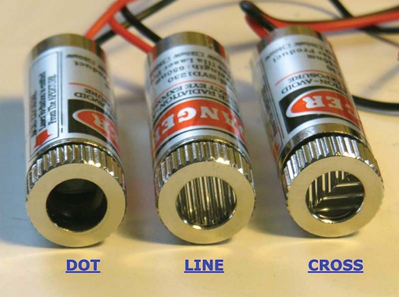
FIGURE 1. Common laser lens options.
Next, I searched the Internet to see what others may have done to integrate laser alignment techniques into their machine shops. I studied three different laser assisted approaches:
- Fixed Mount Laser
- Spindle Mounted, Non-rotating Laser
- Spindle Mounted, Rotating Laser
In this article, I will detail how a fixed mount laser scheme works and can be easily implemented. In Part 2, I’ll show how to design and build a spindle mounted alignment device.
Laser Safety
Before going further, I need to pause for a moment to point out some basic laser dangers and cautions. Even though the relatively low power 5 mw RED lasers are used in this project, they are able to produce extremely bright, tightly focused, high energy beams of light. Such light can damage your vision! DO NOT STARE DIRECTLY INTO THE LASER BEAM AT ANY TIME! Also, use caution when laser centering on highly polished or reflective surfaces as even the reflected light can be very intense and harmful.
Fixed Mount Laser Center Finder
In my Internet travels, I found several experimenters had attached lasers in some fixed location on their machinery or else were in their shop to provide help in center finding and machine setup. One user more or less “randomly mounted” a cross style laser on his mill head, perpendicular to and shining down onto the X-Y table. He just measured the X and Y offsets between the laser cross center point to the actual spindle center point.
With this “calibration data,’ he would then align his work using the laser cross hair, but then “load in” the calibration offset values into the machine so it could find the true part center point. This seemed way too involved and error prone to me, but it did get me thinking about how to use fixed mount lasers with my milling machine.
I determined that if two line-style lasers were accurately positioned and attached to the mill/drill press spindle housing, a cross pattern could be projected onto the table/workpiece surface. As shown in Figure 2, one laser is side-mounted to the spindle housing and projects a line onto the work surface showing the X axis of the spindle.
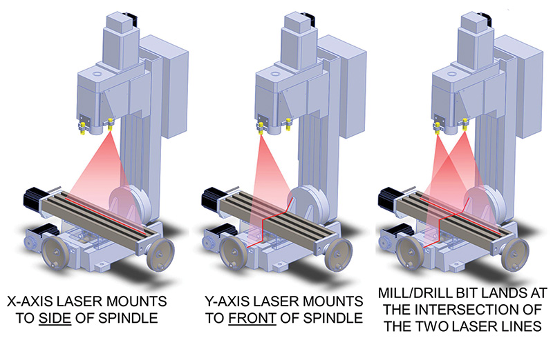
FIGURE 2. Fixed mounted laser scheme.
A second laser is front-mounted to the housing and projects a line onto the work surface showing the Y axis of the spindle. When both lasers are on, two lines are projected onto the work surface. The intersection of the two laser lines will accurately show where the center point of the machine tool will land.
For this to work, one must pay very close attention to the laser alignments to the spindle axis, and laser perpendicularity to the X-Y stage.
Since lasers are cheap and simple laser mounts are straightforward to design and fabricate, a fixed-mount dual laser design can be very inexpensive and easy to implement. This became the first method I chose to implement.
Laser Selection
Don’t waste your time (as I did!) trying to use super cheap laser pointers. I bought some inexpensive laser modules, but found them to be dim and poorly focused. They end up projecting a huge (>2 mm) dim spot that while good for teasing your cat, is not useful for this project.

Instead, I selected a more expensive focusable model I found on eBay from asab.design priced (at the time) at three for $12. These modules are high quality, spec’d to output 5 mw of optical power, yet can still be run from a simple 3-5 VDC power source. They came in a three-module set: one outputting a dot; one a line; and one a cross.
The line and cross units featured an extra lens element (refer back to Figure 1) to transform the output from dot to line/cross. As seen in Figure 3, the modules are a compact cylinder, 12 mm diameter (.47 in) x 36 mm (1.4 in) long. They output a very bright, well focused, red (650 nm) laser beam output. Two line-style lasers are needed for this fixed mount scheme.
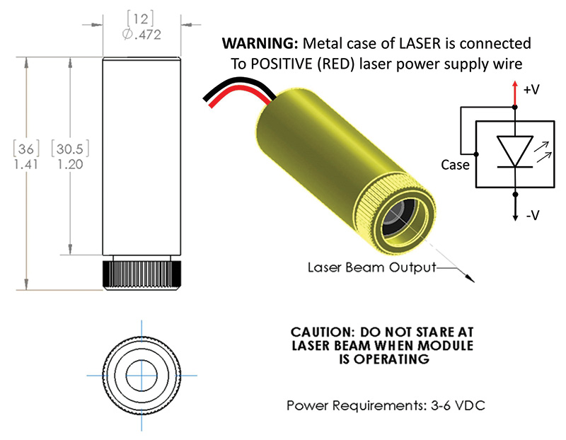
FIGURE 3. Focusable 5 mw laser module.
These laser modules are internally threaded and feature an outer ring that is rotated to bring the beam into focus. I found that these lasers could be well-focused as close as 2.5 inches or so from the face of the laser. Furthermore, their ‘depth of field’ (the distance where they remain reasonably well-focused) seems to be fairly large (several inches). This means that the laser focus can be a set-and-forget one-time adjustment.
I did notice, however, that the output “wobbled” as the lens focus adjustment was turned or touched. This seems to be the result of excessive play in the focus threads. I found that by adding a wrap of Teflon™ plumber’s tape around the focus adjustment threads served to tighten things up.
Making a Fixed Mount Center Finder
To get started, I connected a line-style laser to a battery pack that held a pair of AAA batteries (3 VDC). This got me going quickly so I could begin to experiment. By holding the laser up to the side and the front surface of the spindle housing, I quickly saw how things needed to come together.
I then designed a simple fixed mount bracket that would work for both the front- and side-mount lasers. This bracket is detailed in Figure 4. The drawings are in hybrid English and Metric measurement schemes, as I kept going back and forth from extracting measurements off my Chinese made mill (Metric) while trying to be compatible to the rest of my shop (English).
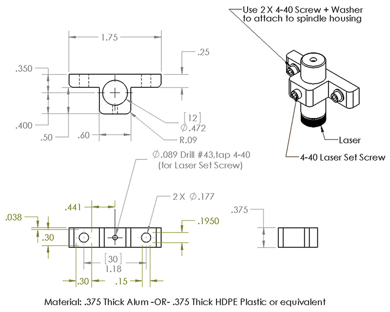
FIGURE 4. Fixed laser mount bracket.
The brackets are designed to be attached to the spindle enclosure using small 4-40 hardware into holes drilled (#43) and tapped (4-40) into the spindle housing. Note that the mounting holes in the brackets themselves are intentionally over-sized for 4-40 hardware, so washers are required. This was done to provide some X-Y as well as rotational play to the bracket so that laser setup and alignment would be easy.
Before any drilling and tapping, I suggest that you power-up the lasers and then temporarily attach them to the spindle housing using double-sided foam tape. With this approach, I was then able to perform some preliminary alignment steps to insure the lasers were located properly with respect to the center line of the spindle, and that they were perpendicular to the table. I developed a set of alignment steps that seemed to work pretty well (see the section on Alignment and Setup).
Once you’re satisfied with the taped locations, you can mark, drill, and tap some permanent holes. WARNING: Take care to check what might be inside and behind the spindle case surface that you are about to drill. In my first attempt, I ended up breaking a tap when it hit a hidden component inside of the housing. I had to move the bracket up by 1/4 inch and try again before I got it right.
As an alternative to drilling and tapping, you can make an adapter plate to utilize existing holes that may already be available in the front and/or side of your machine. As food for thought, Figure 5 shows two plates I came up with that worked for my mill during my prototyping efforts. You can also see that I made one laser bracket from HDPE plastic, and the other from aluminum stock. Both materials worked equally well.
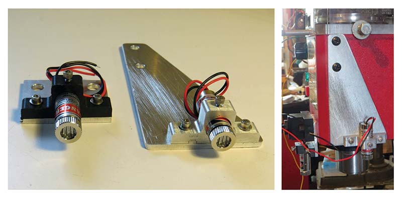
FIGURE 5. Fixed laser mounts; brackets and adapter plates.
Laser Power Supply and Wiring
As shown in the schematic of Figure 6, a two-cell AAA or AA battery holder (with power switch) can power both lasers. Bear in mind that the metal case of each laser is connected to their positive (RED) power wires. This means that once the lasers are chassis-mounted to the mill, the positive wire from the power source will be grounded to the chassis of the machine.
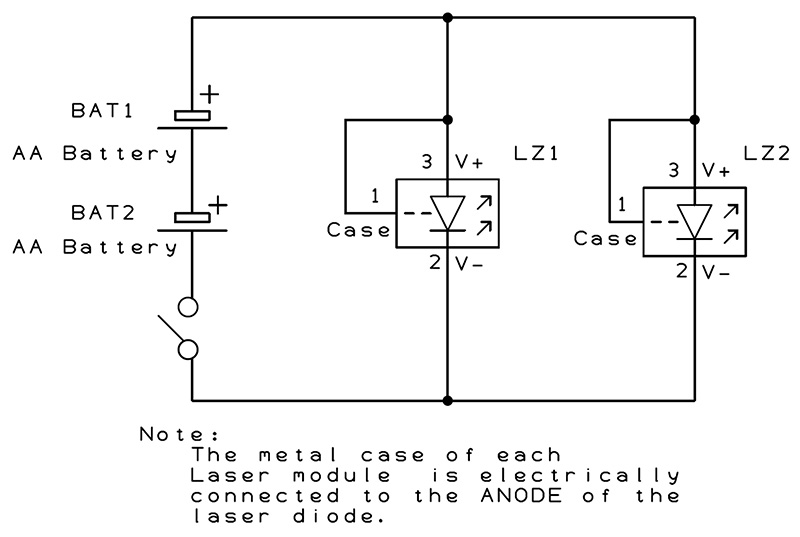
FIGURE 6. Battery powered schematic of fixed mount center finder.
This is not a problem when using a dedicated isolated pair of batteries. However, use caution if you decide to “steal” 5 VDC from an existing device or circuit. You may need to electrically insulate the metal laser bodies from chassis ground to avoid creating a dead short across a ‘borrowed’ power source.

Fixed Mount Center Finder Alignment and Setup
Here’s a guide that details the steps I used for setup and alignment.
1. Place a long 1/4 inch diameter x 7 inch long drill into the 1/4 inch mill collet.
A. You can substitute a dowel or rod, but be sure it’s perfectly true and straight.
2. Apply power to the fixed mount lasers and observe the lines projected onto the table.
Laser Focus
3. Set the Z axis to the elevation where you expect to do most of your center finding. For each laser, rotate just the focus ring on the laser until a fine crisp thin line is traced onto the machine table.
Initial Axis Alignment
4. FRONT LASER: Once focused, rotate the front laser module in its holder bracket until the line on the table precisely traces the Y axis of the machine. When the laser beam is correctly tracing the Y axis, gently tighten the front module set screw.
5. SIDE LASER: Once focused, rotate the side laser module in its holder bracket until the line on the table precisely traces the X axis of the machine. When the laser beam is correctly tracing the X axis, gently tighten the side module set screw.
Laser to Table Perpendicularity
6. As depicted in Figure 7, observe that each laser line is traced onto the long drill in the machine. For each axis, move each laser mount left-right and slightly rotate the bracket as needed until its laser line is exactly centered down the whole length of the drill. Gently tighten the bracket mounting screws, repeatedly checking that drill center tracing is maintained.
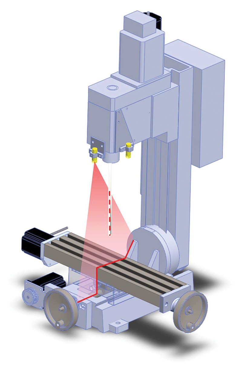
FIGURE 7. Use a long drill to set the X and Y laser perpendicularity. This figure demonstrates Y axis laser alignment.
Fine Alignment
7. Once again, verify that the front and side laser lines traced onto the long drill are both centered and straight (Figure 7). Repeat Step 6 as needed.
8. Place a machinist square onto the table accurately aligned to the X axis of the table. Move the X-Y table location until both laser’s lines just start to trace both the X and Y edges of the square (see Figure 8). Make small tweaks to the laser mounts (Steps 4 and 5) as needed to achieve this result.
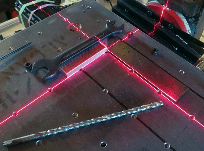
FIGURE 8. Use a machinist square for laser alignment checks.
9. While tracing the edges of the machinist square, move just the Z axis of the machine up and down.
A. If everything is well-aligned, the laser lines on the X-Y table WILL REMAIN STATIONARY as the Z axis is moved up or down.
Final Test
10. Clamp a piece of scrap metal onto the X-Y table and load a small drill bit into your machine. Drill the smallest start of a hole into the surface of the metal to mark the true center point on your machine spindle. If everything is properly aligned, the X-Y laser lines will be dead centered on the hole you just drilled.
11. You should now be able to move the Z axis up and down and observe that the laser cross hairs do not move off center of the drilled mark.
Summary
Complete design details for a fixed mount laser alignment method has been presented. The availability of small low-cost lasers made this project easy and fun to construct. This alignment scheme works well for me and can be readily adapted to any drill press, milling machine, or CNC router.
Next time, we’ll explore how spindle mounted laser center finders can be easily designed and fabricated. See you then! SV
Article Comments