Add a Smart Digital Readout to Your Milling Machine — Part 2
By Tim Paterson View In Digital Edition
Last time, I described my home-brewed touchscreen digital readout (DRO) for my manual milling machine. This time, I’ll cover the details you need to build one yourself. Starting from scratch, it might run about $250 to make a single unit including some one-time costs. A second one would be more like $160.
Everything that went into creating this project is on GitHub (see Resources). From source code to PCB (printed circuit board) files to Windows tools I made like ScreenDesigner (with links to their own GitHub repositories). It’s all there. To build your own unit just like mine, all you really need is what’s in the “Release.”
A Release allows you to download just the essential files without cloning the repository or even figuring out what this Git stuff is all about. Just click on “Latest” in the Releases area on the right side of the main GitHub repository screen, then on the link for SmartDro.zip to download it. Unzip it into a folder. Among other things, you should notice the schematic and parts layout diagram there.
You can find a link for the touchscreen LCD that I used in the Resources. When ordering it from BuyDisplay.com, there are several options that must be specified. You need 5V operation, 6800 parallel interface, resistive touch panel, and pin header connections. You also need the 128 MB serial Flash chip they offer. It comes separately and you’ll need to install it yourself on the display board at U4 (it’s a big SMD that’s easy to solder by hand).
You can generally substitute equivalent parts for those given in the Parts List. However, when ordering the MCU, be sure to get part number ATSAMD21J17D-Axx (typically -AU or -AUT). When I don’t give a distributor part number, it’s because I used parts I had on hand.
I created the schematic and PCB layout in Autodesk EAGLE which is free to use for the hobbyist. I use OSH Park for PCB fabrication; for this design, you get three boards for $40. The project is shared on OSH Park, so you just need to find it on their site using the link in the Resources.
You also need a set of the tiny pinout adapter PCBs. If you have the same pinout as I do, you can order it directly from its shared project (again in Resources).
Otherwise, you’ll need to update the schematic and PCB layout with EAGLE and upload your own version.
A few years ago, I found a couple of SparkFun tutorials on solder paste stenciling and using a skillet for reflow soldering (see Resources). This was prompted by a project that used a gyro chip which was only available in a leadless package that was very hard to hand-solder. Now, I’ve completely converted to using stencils and a skillet for solder reflow for all my designs.
After placing an order at OSH Park, they provide a link to send the design directly to OSH Stencils. I pay the extra to get stainless steel; for this design, it costs about $20. Still, there aren’t many components on this board, and it can be hand-soldered. You just need a steady hand, a fine-point tip, and some magnification for the 0.5 mm lead pitch on the MCU.
After all the SMD components are assembled, the programming connector J13 and serial connector J10 should be added. This is the first chance to check basic functionality but some special equipment is required, starting with a device programmer. I’ve been using Atmel-ICE for several years, but recently tried the Segger J-Link EDU Mini. For around $20, it seems to do all the same things, except it’s limited to 3.3V systems.
Besides the programmer, you also need a TTL-level USB-to-serial converter. I have one from SparkFun I really like that came with a nice long cable and individual pin connectors on the end; it was only $8 at the time (see the Recommended Equipment sidebar). The PCB markings on J10 match the markings on this cable.
Recommended Equipment
| Device | SparkFun Part No. | Digi-Key Part No. |
| Segger J-Link EDU Mini Programmer | PGM-15345 | 899-1061-ND |
| USB-to-TTL Serial Cable | CAB-17831 | 1568-CAB-17831-ND |
For example, the cable connector labeled “TXD” connects to the PCB pin labeled “Tx.” (This means the PCB could be considered labeled backwards, as its “Tx” pin receives serial data.) You power the PCB by connecting the VCC connector to the +5V pin. Or, you can install the power switch and power it from the micro-B USB connector.
Figure 1 shows the programmer and serial cable connected.
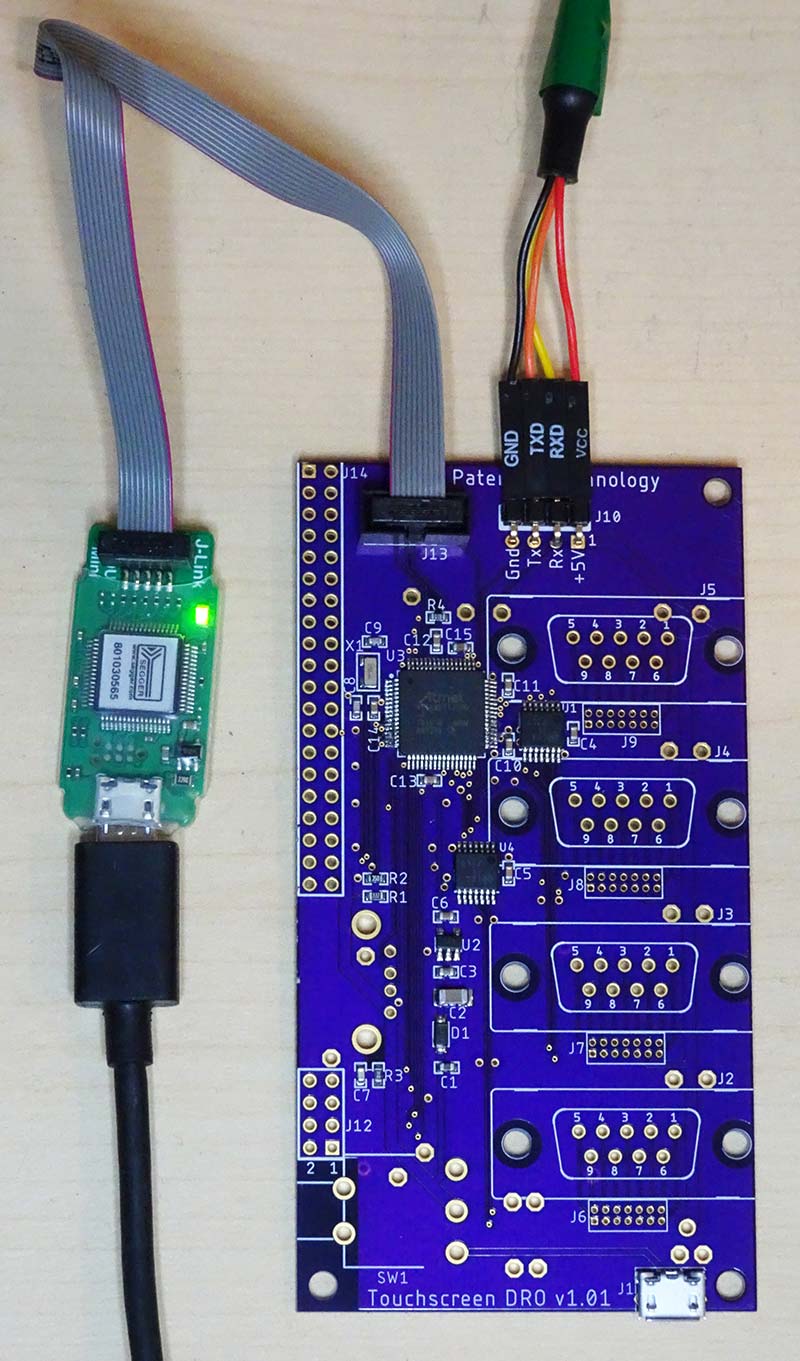
Figure 1 – Setup for initial programming, before most through-hole components have been assembled.
Before you can “burn” the firmware into the MCU Flash memory, you need a terminal program running on your computer for the USB-to-serial converter. I’ve written my own for Windows and included it in the Release as ComTest.exe. Whatever you use, it needs to be set for 500,000 baud.
The software for the Segger programmer comes with two memory Flashing programs called J-Flash and J-Flash Lite. Either one is easy enough to use without reading the manual. You can also program the MCU Flash using Microchip Studio, but that’s a big download if you don’t have it already.
Just choose the device (Microchip ATSAMD21J17) and select the DRO.hex file from the Release.
If everything goes right, the terminal program will spit out “DRO version x” to tell you the MCU is up and running. Typing the “x” key into the terminal program should cause the MCU to reset, reprinting the message.
Once this is working, it’s time to power down and complete the assembly of all the through-hole components. Several components outlined on the top side of the board are actually placed on the bottom. Look at Figure 2 to make sure you mount everything on the correct side of the board.
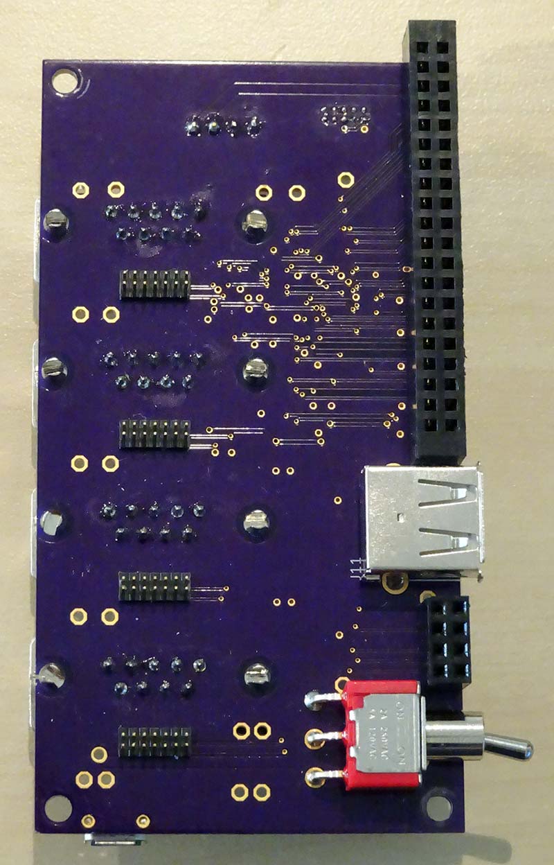
Figure 2 – Quite a few of the through-hole components mount on the back side of the PCB.
Final Programming & Calibration
With PCB assembly complete, the board should be plugged into the display module for the final steps. As the display can take 500 mA by itself (and my three position sensors combine for another 200 mA), be sure to use a strong USB power brick that puts out a full 5V under load.
The remaining steps are to program the display’s serial Flash memory (you installed that, right?) with the images and fonts, and to calibrate the touchscreen. These steps require the serial connection again, but once they’re done, it won’t be needed anymore. Don’t connect the +5V pin on the serial connector when the unit is powered from the USB port.
The images and fonts are programmed by copying the files Screen.bin and Fonts.bin from the GitHub Release to the root of a USB Flash drive. Plug this drive into the USB port on the PCB. Now at the serial console, just type “f” and you should get the response “Loading font…” which will finish in just a second. Next, you type “i” with the response “Loading image…” and then wait for a bit.
There’s over 4 MB of images and it takes around 40 seconds to program them into the serial Flash. Once the fonts and images are programmed, you can type the “x” to reset the MCU and the main screen should appear. Figure 3 shows a screenshot of the serial console.
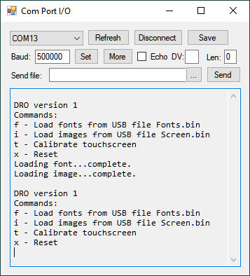
Figure 3 – Screenshot showing using the serial console to load fonts and graphics into the display Flash.
The touchscreen won’t work yet because it needs to be calibrated. Type “t” at the serial console and the touch calibration screen appears. This simple image is generated by the MCU firmware, so it doesn’t rely on the serial Flash to be programmed.
To get a good calibration, use something pointy and soft-ish (plastic) to apply a medium pressure at the crosshairs on the screen. After touching the three locations, you can touch anywhere on the screen and get a cursor that will show you where it thinks you’re touching.
Just landing anywhere within the cursor is decent calibration. You can test the effect of pressure on the calibration; you need to press hard enough for the cursor to stop moving.
Buttoning Up
The Release includes STL files for the two plastic bezel pieces that can be 3D printed. The back plate is 1/8” aluminum; I’ve included a fully dimensioned drawing in the Release. I didn’t include a drawing of my mounting bracket, as it’s dependent on what you’re mounting it to. I have included the full Fusion 360 model which has the bracket and even the CAM I used to machine it. You can build it the same way or modify the design any way you want.
When assembling the screen into the plastic bezel, the standoffs fit very tight into the corners. Figure 4 shows how I stacked standoffs to make them accessible.
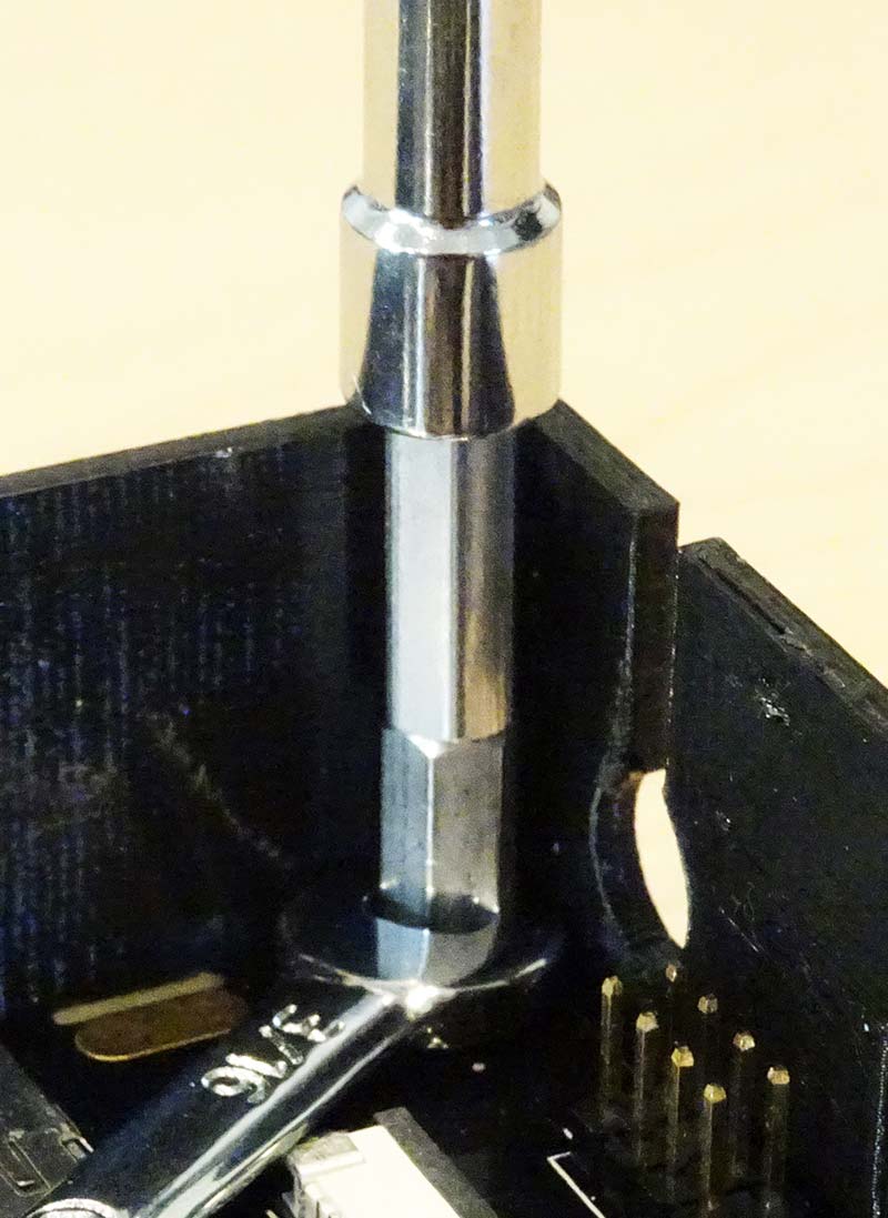
Figure 4 – Stack standoffs to tighten them in the corners. A wrench or pliers may be needed to separate them.
The corner where the MCU PCB mounts uses a 7/16” standoff, while the rest are 3/4”.
Before installing the MCU PCB, put 1/4” standoffs in the holes above and below the D connectors. These should be held on with nylon-insert lock nuts to ensure they don’t get loose.
Pushing the PCB onto its connectors is slightly tricky. The power switch handle rides down a slot in the bezel, but the plastic still needs to be bowed out a bit for the USB-A connector. Once you have the pins lined up, you’re home free.
Secure the corner with a 1/4” standoff, which makes the height to the back panel 7/16” + 1/16” (PCB) + 1/4” = 3/4” — the same as the other mounting points. Figure 5 shows it in place.
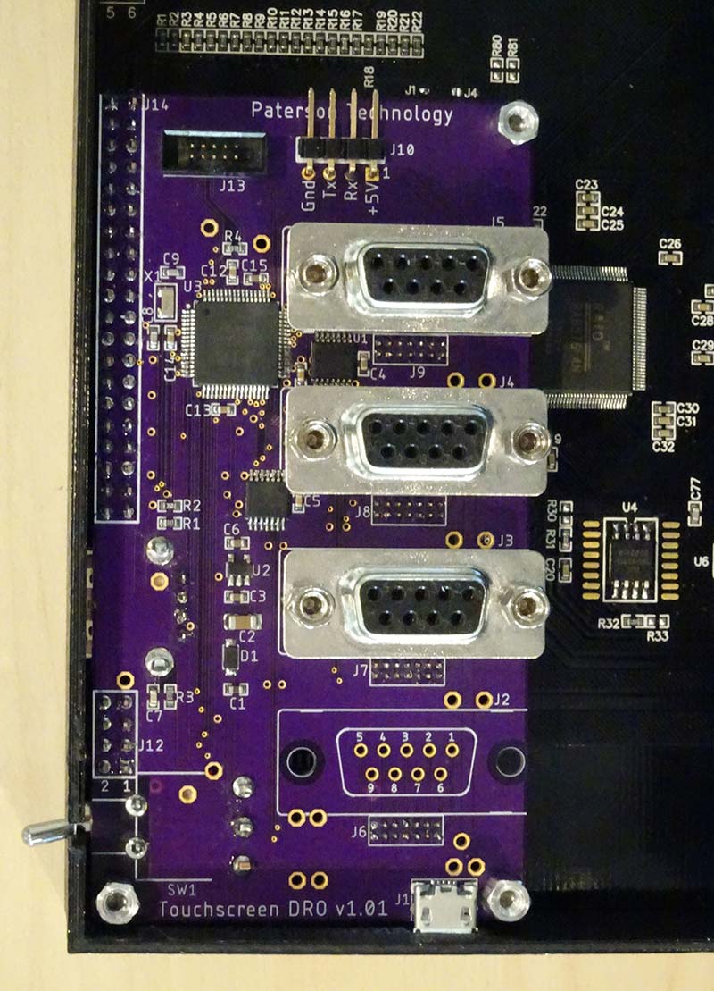
Figure 5 – The MCU PCB is nestled in its corner, fastened with one standoff. Note U4 on the main board has the 16 MB Flash memory installed.
When you’re ready for final assembly of the back panel, it’s important to affix it with all 11 screws. The two above and below the D connectors are critical support when you push the position sensor connectors on. The four that go into the bezel keep the two halves from flopping around at the seams.
Putting It to Work
The moment of truth is connecting your position sensors and seeing the readouts change when you crank the handwheels. The order of the connectors on the back is the same as the displays on the front, X axis on top. The sign (positive or negative) for a given direction of travel will be random.
On my mill, the handwheels are marked so X increases as the table moves left, Y increases as the table moves away from me, and Z increases as the cutter is lowered. The original Grizzly DRO used the same sign convention. With a new setup, odds are some of these will be backwards, which we can correct in the Setup menu.
Touch the Setup button in the upper right corner; you’ll get the screen shown in Figure 6.
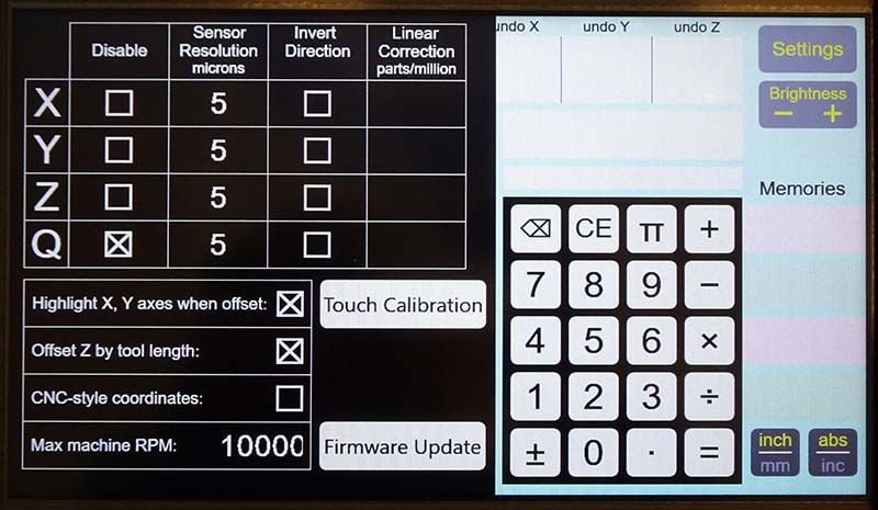
Figure 6 – Initial Setup screen. Sensor resolution and direction are the most critical.
Now you can simply touch Invert Direction for an axis to correct any that were moving backward. You can also disable an axis altogether; for example, if you don’t have a Z position sensor. If your sensors don’t have the typical five micron resolution, you can change it here.
This would be a good time to talk about how to enter and use values. Tapping digits on the keypad enters a number into the calculator. Then, tapping on any field that uses a number copies it there.
If you have two micron sensors, just tap “2,” then tap the resolution box for each axis to change them all. This applies to any numeric field on any screen. You could enter a number, then tap one of the memory fields along the right side, and the value will be kept and displayed there.
To move a value back to the calculator, the calculator display must be blank. You get that with the CE (Clear Entry) key. So, tapping CE and a memory or CE and an axis resolution field will copy either of them back to let you use it in a calculation. The same rules apply to the axis displays and tool parameters on the main screen.
Some fields like the memories or the tool parameters are “blank on zero.” If you’re done with a value in a memory and don’t want to see it there anymore, enter 0 in the calculator and tap the memory. Instead of showing the value zero, the display for that field is blanked. Blank on zero does not apply to some fields, like axis resolution or axis position.
Most of the remaining settings are fairly self-explanatory. I do want to mention the “CNC-style coordinates.” On a CNC mill, the direction of both the Y and Z axes is reversed. This makes the coordinates match the normal orientation in a CAD program, where increasing Z is up.
You can see there is an option to select this coordinate system.
What’s important here is that checking the box does NOT reverse Y and Z for you. You still have to do that with Invert Direction. This box is for offset calculations (for example, whether to add or subtract the tool length to / from Z).
When you’re done with the Settings menu, tap the Settings button in the upper right again. This will save any changes to a Flash memory dedicated to holding the parameters, and then bring you back to the main screen. If things are set up right, turning the handwheels will change the readouts in the expected directions.
This would be a good time to experiment with zeroing the axes, setting them to a specific value, and copying their current reading back into the calculator. You may find there’s an easy mistake to make: You intended to copy an axis position to the calculator but didn’t tap CE first to clear the calculator display.
The axis display will be set to the calculator value instead of the other way around. Fortunately, there’s an easy fix! Tap the Undo button above the calculator for the affected axis and the readout is restored.
Next, give the radius offset feature a try. Enter the diameter of your favorite end mill in the calculator and tap “Dia.” in the tool parameters. Then, just below that, tap which side of the workpiece you’re cutting, and note the change in the affected axis.
Tool Libraries
If you don’t measure your tool lengths and don’t want the DRO to help calculate feeds and speeds (for which it needs a flute count), then you might prefer to just manually enter the diameter each time you change tools. If that’s the case, go ahead and skip this section!
If you want the DRO to keep a permanent tool library for you, press the “. . .” button to the right of the tool parameters (refer to Part 1 of this article). To manually enter a tool, it must have a tool number (1-999) and any one other field set. You set the numeric fields in the usual way touching the entry row at the top with the value in the calculator.
To enter a 1/32” end mill, for example, you could enter “1 ÷ 32 =” then tap the Dia. field. The field display is truncated to three decimal places, but you can see the full value is still there by tapping CE and the field to copy it back. (Internally, the value is stored in double-precision floating point.)
To enter a description, tap anywhere in the description field and an onscreen keyboard appears. Be sure to tap the Done button on the keyboard itself — not the one in the upper right corner — to save your changes.
Of course, there’s an alternative to entering all your tools on the touchscreen: Import them from a USB Flash drive. By tapping the Import/Export button in the upper right corner of the tool library screen, you bring up a file browser. In Figure 7, it’s displaying the contents of a Flash drive of mine.
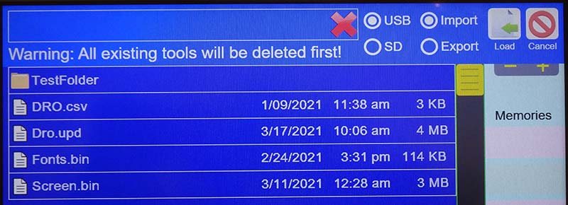
Figure 7 – Contents of the Flash drive on the USB port of the DRO. The file DRO.csv can by imported to populate the tool library.
The file DRO.csv has my current tool library in a “comma-separated values” format. The file was actually written in Microsoft Excel, and you can see a portion of its contents in Figure 8.
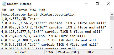
Figure 8 – A sample of the contents of a tool library file. It was exported to Microsoft Excel.
By tapping the file name in the list and then the Load button in the upper right, all 68 of my tools are instantly loaded.
So, where did this file come from? A few years ago, I created an Excel application using macros that translates between the different file formats of my tool libraries. Fusion 360 has the master library, which I can export and load into Excel. My macros then churn out versions that can be imported by my Tormach CNC mill, G-Wizard program, and now the Smart DRO.
I’ve shared my Tool Library Manager on GitHub (see Resources), so anyone can use it. It’s designed to be easily adapted to other export formats and not be limited to just the machines and programs I use.
If you don’t have a need to share tool libraries, Import/Export can just be viewed as a way to back up the tool library you manually entered into the DRO. The unit has a microSD card slot, and back in Figure 7 you can see there’s a choice for “SD” instead of “USB.” It’s not very convenient to take cards in and out of the slot, but you can just leave one in there and use it as a backup.
When you make changes to your tool list, you would just go ahead and export it to the microSD card.
Note that when you export a file, the file system needs a date and time to timestamp it. Selecting Export will cause a Set button to appear to set a clock in the DRO. The clock will remain set until the power is switched off.
Firmware Update
Back on the Settings screen in Figure 6, there’s a large white button labeled Firmware Update. This will bring up a file browser that’s similar to the one used for Import/Export shown in Figure 9.
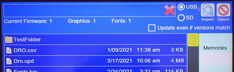
Figure 9 – Browsing for a firmware update file. It’s the one with the “.upd” extension.
The build process for the DRO firmware automatically creates an update file with a “.upd” extension, which you see in the file list. This file combines all three elements that were programmed separately when the unit was first programmed: firmware, fonts, and images. Each Release on GitHub includes the corresponding update file as a separate download.
When you select the file and tap the “Inspect” button, the DRO verifies it’s a valid update file and displays the versions of the components it contains as shown in Figure 10.
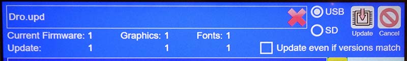
Figure 10 – The firmware update file has been opened and verified. You can compare the current DRO versions with those in the file.
In this case, all the components in the update file match the current firmware in the unit.
If you were to tap what is now the “Update” button, it would update the MCU firmware from the file, but the graphics and fonts would not be updated because they’re already correct.
You can force the graphics and fonts to update anyway by checking the box, but this should only be needed if a previous update had gone wrong.
And We’re Done!
I enjoyed working on this project, learning lots of new stuff, and maybe — most of all — declaring it finished! I also like to help others take advantage of what I’ve learned, which is why I’m writing about it and sharing it all on GitHub.
The GitHub project includes Discussions and Issues sections where you can make comments and ask questions. I’ll help if I can. SV
Parts List
| Qty | Reference | Description | Package | Digi-Key Part No. |
| 1 | C1 | 10 µF Capacitor | 0603 | |
| 1 | C2 | 100 µF Capacitor | 1206 | 1276-1782-1-ND |
| 3 | C3, C6, C15 | 1 µF Capacitor | 0603 | |
| 7 | C4, C5, C10, C11, C12, C13, C14 |
0.1 µF Capacitor | 0603 | |
| 1 | C7 | 4.7 nF Capacitor | 0603 | |
| 2 | C8, C9 | 10 pF Capacitor | 0603 | |
| 1 | D1 | MBR120VLSFT or MBR120LSFT Diode | SOD123F | |
| 1 | J1 | USB microB Connector | 609-4616-1-ND | |
| 4 | J2, J3, J4, J5 | DE-9F Connector | L77SDEH09SOL2RM8-ND | |
| 4 | J6, J7, J8, J9 | 14-pin 50-mil Header | 2057-HPH2-A-14-UA-ND | |
| 4 | J6, J7, J8, J9 | Optional Socket | 609-3756-ND | |
| 1 | J10 | Four-pin 100-mil Header | Right Angle | 1849-PR20204HBNN-ND |
| 1 | J11 | USB-A Connector | ED2989-ND | |
| 1 | J12 | Eight-pin 100-mil Socket | S7107-ND | |
| 1 | J13 | 10-pin 50-mil Header | 1175-1627-ND | |
| 1 | J14 | 40-pin 100-mil Socket | S7123-ND | |
| 1 | R1 | 33K Resistor | 0603 | |
| 1 | R2 | 11K Resistor | 0603 | |
| 1 | R3 | 1M Resistor | 0603 | |
| 1 | R4 | 1K Resistor | 0603 | |
| 1 | SW1 | Toggle Switch | EG2362-ND | |
| 2 | U1, U4 | 74LCX14 Logic IC | TSSOP14 | MC74LCX14DTR2GOSCT-ND |
| 1 | U2 | MIC5504-3.3 Voltage Regulator | SOT23-5 | 576-4764-1-ND |
| 1 | U3 | SAMD21J17D MCU | TQFP64 |
ATSAMD21J17D-AU-ND |
| 1 | X1 | 32.768 kHz Crystal | 3.2x1.5 mm SMD | 2195-CM7V-T1A-32.768KHZ-7PF-10PPM-TA-QCCT-ND |
| 4 | 4-40 x 3/4” Hex Standoff | 1772-1003-ND | ||
| 3 | 4-40 x 1/4” Hex Standoff | 1772-1230-ND | ||
| 1 | 4-40 x 7/16” Hex Standoff | 1772-1001-ND | ||
| 11 | 4-40 x 1/4” Screw | |||
| 2 | 4-40 Nylon Insert Lock Nut |
From BuyDisplay.com
1 ER-TFTM101-1 LCD w/options: pin header 6800 parallel; 5V; resistive touch; pin header microSD.
1 Winbond W25Q128JV serial Flash (install on LCD at U4).
Resources
Project on GitHub
https://github.com/TimPaterson/TouchscreenDigitalReadout
BuyDisplay LCD
https://www.buydisplay.com/serial-spi-i2c-10-1-inch-tft-lcd-module-dislay-w-ra8876-optl-touch-panel
OSH Park - Main PCB
https://oshpark.com/shared_projects/jTW1CESl
OSH Park - Pinout Adapter
https://oshpark.com/shared_projects/7Whg99iS
SparkFun Tutorial
https://www.sparkfun.com/tutorials/59#Hot%20Plate%20Reflowing
Library Manager on GitHub
https://github.com/TimPaterson/CNC-Tool-Library-Manager
Downloads
202006-Paterson.zip
What’s In The Zip?
DRO Schematic
DRO Layout
CNC Tool Library Manager Master
Article Comments