Add a Smart Digital Readout to Your Milling Machine — Part 1
By Tim Paterson View In Digital Edition
If you already have a manual milling machine with a digital readout (DRO), then see if any of these experiences I’ve had seem familiar:
- I carefully establish my starting point using an edge finder and zero the corresponding DRO axis. I forget to account for the radius of the edge finder until I’m ready to cut and notice it just doesn’t look like the cutter or drill is in the right place.
- I set zero on the first axis, then crank the table so I can apply the edge finder to another side. Once I have it nicely aligned, I hit the zero on the wrong DRO axis — the one that I just set — and have to go back and do that one over.
- With both X and Y axes all set up, I’m ready to start cutting with my favorite roughing tool: a 3/8” carbide end mill. If my drawing says to put an edge at, say, 2.145”, I have to add (or maybe subtract) the cutter’s 0.1875” radius to get the correct position to set the DRO. It’s too many digits to trust doing it in my head, so I end up writing addition or subtraction problems at all the dimensions of my drawing.
I mentor for the FIRST robotics club at a nearby high school (go Ragin’ C-Biscuits!) and they have two big Bridgeport mills, each with an ancient DRO. One of the displays actually has to warm up before it shows anything. Both of them have broken X axis position sensors. So, one day I was surfing the web to see what it would take to replace them, and I got to thinking that I could build a DRO — at least the display head.
This project idea had several things going for it. For starters, I’d get to fix the common pitfalls I just mentioned. I’d also been reading about touchscreen projects on the pages of Nuts & Volts and thought maybe it was time for me to get on the bandwagon. This seemed like a project I could actually finish (unlike, say, my robot) and I did, in about six months.
Feature Set
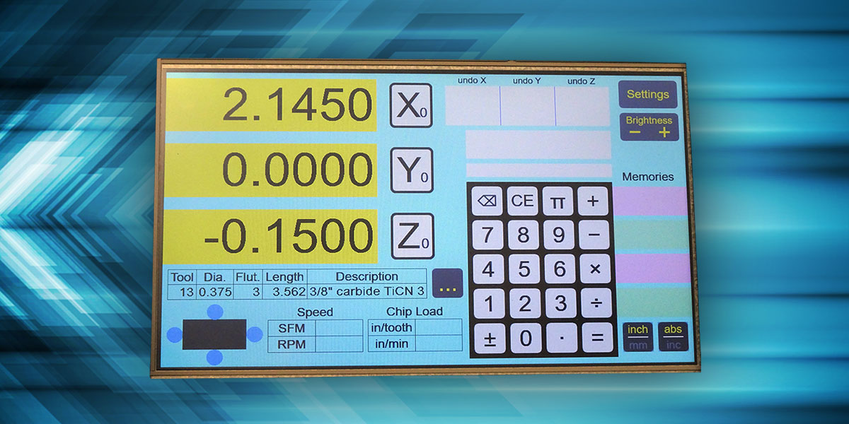
How does my own design make the DRO easier to use? The crux is for the DRO to know the diameter of the tool. Figure 1 shows the main screen, and you can see below the Z axis readout there’s a small table with entries labeled “Tool,” “Dia.,” etc.
Figure 1 – Main screen of the digital readout.
The tool diameter can be entered by simply tapping in the value on the touch keypad, and then tapping the “Dia.” column.
However, this is not enough because it needs to know what side of the stock is being cut — whether to add or subtract the tool radius. Right below the tool table is a dark rectangle with a circle on each side. That represents a top view of the workpiece with the cutting tool on any of its four sides. Touching the spot where the tool contacts the work enables a radius offset for the corresponding axis.
Two adjacent sides can be selected at once, offsetting both X and Y. Figure 2 shows the cutter offset enabled on two sides.
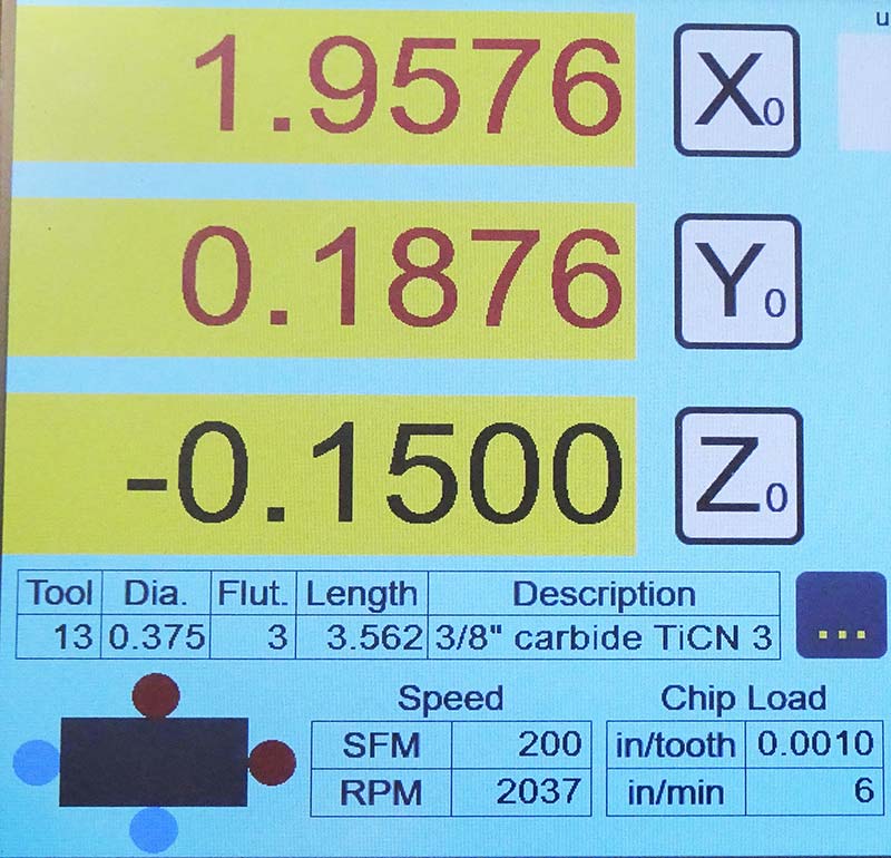
Figure 2 – Cutter radius offset is enabled for both the X and Y axes.
The displays have some added color to remind you that the cutter offset is in effect. (The display resolution is 0.0002”, so it can’t display the exact offset of 0.1875”).
It was somewhat of an afterthought that I realized I could easily add basic calculations for speeds and feeds. By entering a desired surface feet per minute, the corresponding RPM is calculated for the given tool diameter. By adding an entry for the number of flutes on the tool, then the feed rate can be calculated in inches per minute for a chip load that you enter in inches per tooth. So, how would you know if you’re cranking at the right feed rate? Anytime you crank the X and/or Y axes, your current feed rate appears in the dark rectangle.
You’ll also notice the tool info table has an entry for length. If you have a way to measure the exact length of your tool as mounted in the spindle (such as the Tormach Tooling System), then this will automatically adjust your Z axis as you change to tools of different lengths.
The display allows you to directly enter these tool specifications on the main screen using the keypad as you change tools. However, the real power of this is to keep a tool library so you only have to enter the information once. The unit can store 500 tools in Flash memory, giving you access by a tool number that you assign or by scrolling through a list.
By tapping the “...” button to the right of the tool info table, you open the full tool library as shown in Figure 3.
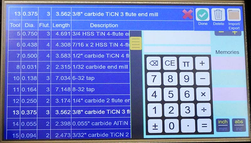
Figure 3 – Tool library screen, with selected tool highlighted in the scrolling list.
Here you can enter new tools, update existing ones, and select the next tool you’re using. The list can be dragged up and down with your finger, or the yellow scroll thumb can be dragged to move through the list rapidly.
f you have a lot of tools or you want to stay synchronized with another tool library (for example, you use G-Wizard to calculate feeds and speeds), then manually entering all your tools isn’t very convenient. That’s why there’s a USB port for a Flash drive that allows you to import your tool list from another source. It accepts a “comma separated values” (CSV) format that can be directly written by Excel. It can also export the list to save as a backup or transfer to another device or program.
But enough about tools. What about that problem of zeroing the wrong axis? Back in Figure 1, you can see areas in the upper right of the screen labeled “undo X,” etc. Every time you change the origin of an axis, the difference is recorded in the undo list. It saves eight levels of undo, showing the last three on screen. Like my original Grizzly display head, it supports two coordinate systems (called “abs” and “inc,” although there is no significance to the names) with separate undo lists for each one.
Finally, there’s the keypad with calculator. You can tap an axis display to load a value into the calculator and just as easily move a calculated value into a display. There are four memories whose contents are always visible. Plus, the backspace key makes corrections easy while you enter.
Mill Interface
As I shopped around for DRO kits, one thing that seemed consistent was that the position sensors connect to the display head using one nine-pin D connector (like a serial port) for each axis. What wasn’t consistent was the pinout of the connector — when you could find it. The basic signals are two power pins providing 5V and two position encoder signals called A and B. These could be on any pins, and sometimes the A and B signals were each a differential pair: A+, A- and B+, B-.
To have a chance at dealing with all the variations, I designed the circuitry to pass the connections for each axis through a small 14-pin 50 mil header. That’s enough to gather the nine pins of the D connector and the four power and signal connections to the circuitry. A separate tiny circuit board (0.25” x 0.36”) routes the four necessary connections.
I use OSH Park for printed circuit boards (PCBs). They charge a flat rate of $5 per square inch to deliver three boards. The price of this little interface board is 45 cents, shipping included! I could splurge and pay double for their “swift” service, and the price would still be less than a buck. That gets me all three I need for X, Y, and Z.
The tiny pinout adapter PCBs can be installed in one of two ways: the PCBs can be soldered directly to the pin headers, making them permanent; or the PCBs can be put on female sockets that plug into the pin header. I’ve done it each way on the two prototypes I’ve made, as shown in Figure 4.
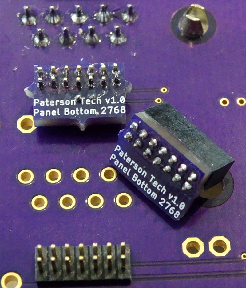
Figure 4 – The tiny interconnect PCB can be soldered directly to the pin header or be removable using a socket.
I couldn’t find documentation on the pinout for my Grizzly DRO, but it wasn’t hard to figure it out with a voltmeter. Probing around the open connector on the DRO head quickly revealed where power and ground were. I then had to make a little adapter that gave me access to the pins while the position sensor was plugged in.
With ground known, I easily found the two pins that changed state when I turned the axis handwheels. The result: ground is pin 2; +5V is pin 7; A is pin 6; and B is pin 8 (A and B are interchangeable). I use that pin order to name the interface, so I call it type 2768.
A typical position sensor has a resolution of five microns (about 0.0002”). If an axis handwheel was turned at a constant speed, you would see a square wave on the A and B signals, with a 90° phase shift. The direction of the phase shift — whether B is leading or trailing A — gives the direction of travel. This is the classic quadrature signal pair of an incremental encoder. Each transition on either A or B is one step at the resolution.
For my own mill, I replaced an existing display and used the OEM-installed position sensors. The sensors are available separately. It appears there’s optical ones you have to buy to length and magnetic ones that can be cut to length.
Hardware Design
I decided I needed a 10” touchscreen, and the only candidate I could find was at BuyDisplay.com. The unit was about $85 plus a surprising $30 for shipping from China. That includes a resistive touch overlay and a control board the size of the screen that has a graphics controller, 16 MB of video RAM, a resistive touch controller, and microSD card slot. I also ordered a 128 Mb (16 MB) serial Flash chip from them at the same time.
I love hardware design and making purpose-built digital circuits, so of course this would be no different. The schematic is shown in Figure 5.
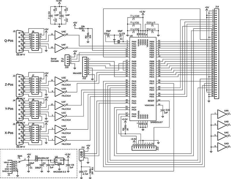
Figure 5 – DRO schematic. A few chips and lots of connectors.
It’s not much more than a Microchip SAM D21 microcontroller unit (MCU) and a bunch of connectors. The PCB made from this design plugs directly into the interface connectors on the touchscreen and is secured with a standoff.
Along the left side of the schematic, you see the interface to the position sensors. I included a fourth “Q” input for a quill but haven’t used it. U4, J2, and J6 are not needed at all to just have three input sensors for X, Y, and Z. I discovered the 74LCX logic family while researching for this design; it’s perfect for interfacing the 5V sensors to the 3.3V MCU.
One part of the schematic I’d like to explain is the power-off detection. In the lower left corner, you see the power circuit in dashed lines. The touchscreen takes about 500 mA at 5V, while the MCU runs on 3.3V. When the power is switched off, diode D1 blocks capacitor C2 from discharging rapidly into the touchscreen, holding up the 3.3V supply for the MCU briefly. Near the top of the schematic, R1 and R2 are dividing the 5V supply by four.
What’s not obvious is that the divided voltage is being routed to an analog comparator in the MCU with an accurate internal reference of 1.1V. The output of that comparator is on MCU pin 29, which is wired around to the non-maskable interrupt (NMI) on MCU pin 17.
So, when the 5V supply drops to 4.4V, NMI triggers. Software takes over and quickly saves the current axis positions in Flash memory so they can be restored on power-up. I’ve measured 5-10 ms from the time NMI triggers until the 3.3V supply begins to droop; plenty of time to get the work done.
Figure 6 shows the front and back of the assembled prototypes.
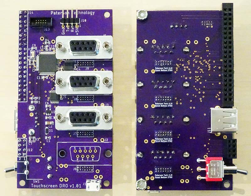
Figure 6 – Front and back views of the assembled PCB.
The front of the PCB (which will actually face out the back side of the assembled unit) has a four-pin connector on the top for a TTL serial connection. At the bottom is a USB micro B jack just for power. On the back of the PCB, you can see the four tiny interconnect PCBs for matching the position sensor’s pin-out.
There’s also the standard USB-A connector where a Flash drive can be attached.
Software Overview
I wrote the software for “bare metal” — no operating system or support libraries (except standard C runtime). I’ve had previous experience with some of the software elements like USB drivers and a FAT file system for the Flash drive. However, the graphics and touch drivers were all new to me and took a lot of development time.
When I ordered the touchscreen, I added a font serial ROM option. After a little experimentation, I concluded that the fonts it provided were of no help. Sizes were very limited and too small, and the fonts themselves were ugly.
My solution was to write a Windows app to generate font bitmaps from any Windows font. Called FontGenerator, you can check it out on GitHub (see Resources). I ended up using it to give me four fonts in heights of 24, 36, 48, and 96 pixels. The largest one is only used for the axis readouts and doesn’t have a full character set (just space through ‘9’, 0x20-0x39).
The RA8876 graphics controller chip used on the touchscreen has what they call a color expansion function. It will copy a rectangular black and white bitmap and substitute any two colors for one and zero (or you can choose to leave existing pixels unchanged on zero).
This is perfect for writing individual characters in full color, and it’s extremely fast.
My next problem was designing the graphics for the touchscreen. Not only did I need graphics, but I needed the size and location of things that acted as hotspots for touch or text areas. I searched for a tool that would work and didn’t find anything. So once again, I ended up writing my own.
It’s a Windows app called ScreenDesigner, also available on GitHub. It doesn’t have graphical objects you can drag around on the screen and place visually — that’s just over my head. Instead, it’s essentially a programming language for graphics using XML. While creating the graphics, I used an XML text editor and as soon as the XML was saved to disk, ScreenDesigner updated its image. This was actually very usable. If I was tweaking the position of something by a few pixels, I could type in a new number, save with Ctrl-S, and it would instantly appear in its new position.
Figure 7 shows about half the graphics I created for the touchscreen.
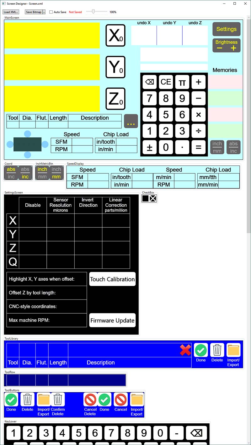
Figure 7 – Some of the graphic images for the DRO, which all get loaded into the 16 MB Flash memory.
Most of it is 16-bit color, but the black and white images were done in eight-bit color to save upload time. Several images (see the first row after the main screen) are overlay arrays that are copied onto another screen.
For example, when you toggle between inch and millimeter units, the button you’re pushing is overwritten by one that indicates the current state in yellow (the two-element array of buttons is indexed by the value of a Boolean). There are two-, three-, and four-element image arrays sprinkled in among the graphics.
FontGenerator and ScreenDesigner each spit out a binary file with fonts or images and a header file with all the data the program needs to use them. The two binary files get loaded into the serial Flash memory on the LCD. On startup, the RA8876 is instructed to copy the serial Flash to video RAM, which it can do in one command. The total graphics size is about 4 MB, using only a quarter of available serial Flash and video RAM.
There’s isn’t room here to go further into the inner workings of the software. It’s all on GitHub if you’re interested (see Resources).
Enclosure
I modeled the touchscreen and electronics in Autodesk Fusion 360: a wonderful free-to-the-hobbyist CAD program. I used it to design an enclosure with 3D-printed bezel and an aluminum back. Unfortunately, the enclosure is about 1/4” longer than my 3D printer can print, so I had to split it into two. Figure 8 shows the two plastic pieces, which would be interchangeable except for the cutouts in one of them.
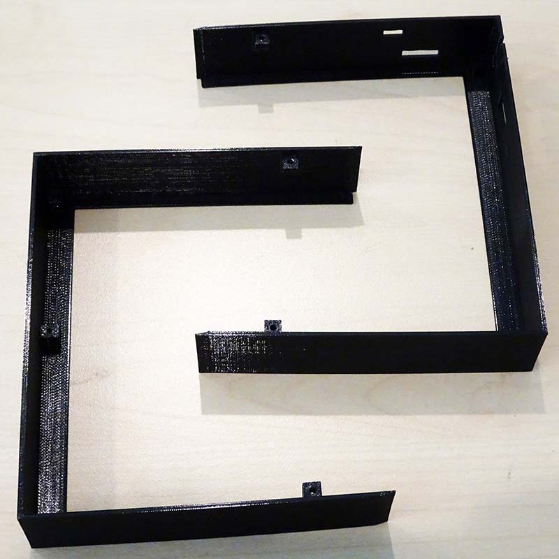
Figure 8 – The two halves of the screen bezel, 3D printed in PETG.
Figure 9 has a close-up of one of the small ears that the back plate mounts to.
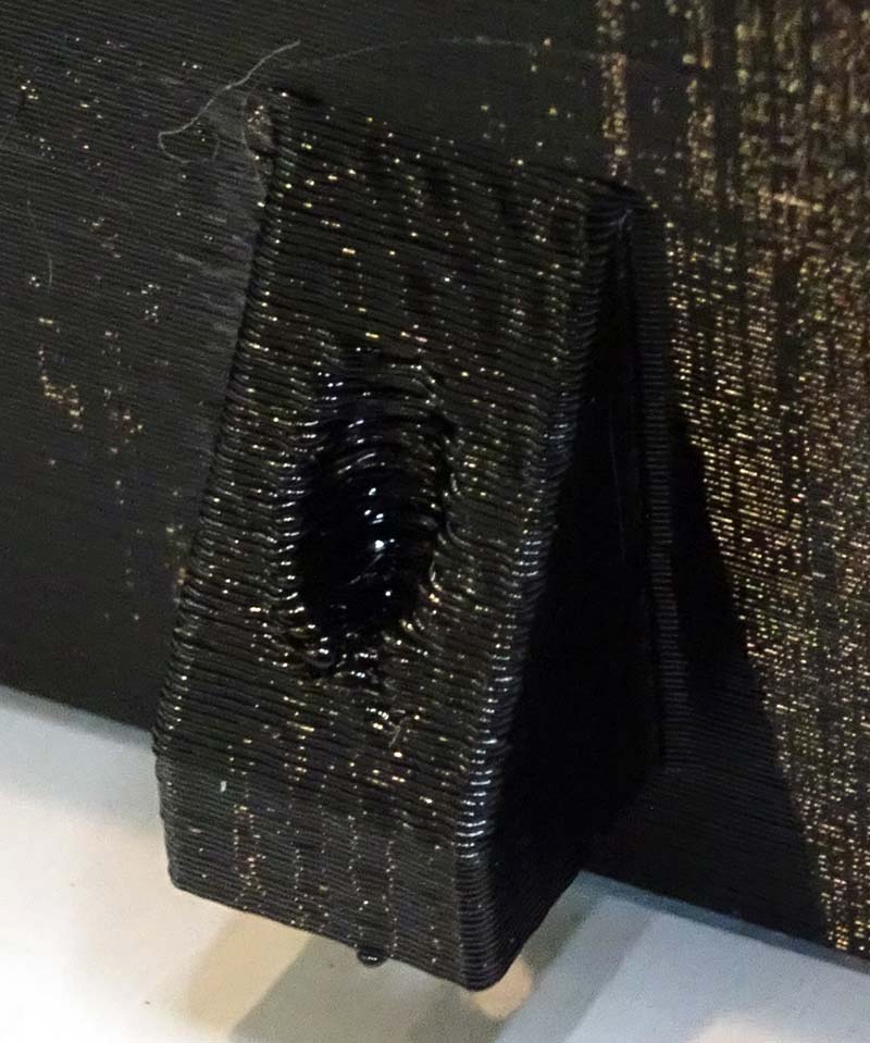
Figure 9 – Mounting tab on the bezel showing 4-40 thread printed in.
I was hoping you could see that it was printed with the 4-40 thread built in. The back side of the bezel pieces have similar threaded posts at all the mounting points of the touchscreen PCB.
The threads of the standoffs go through the back of the PCB into the bezel which gives them a nice tight fit like a nylon lock nut. Except for acting as a nut in the way, the plastic pieces are not structural.
The back plate and its mounting bracket shown in Figure 10 provide all the structural support.
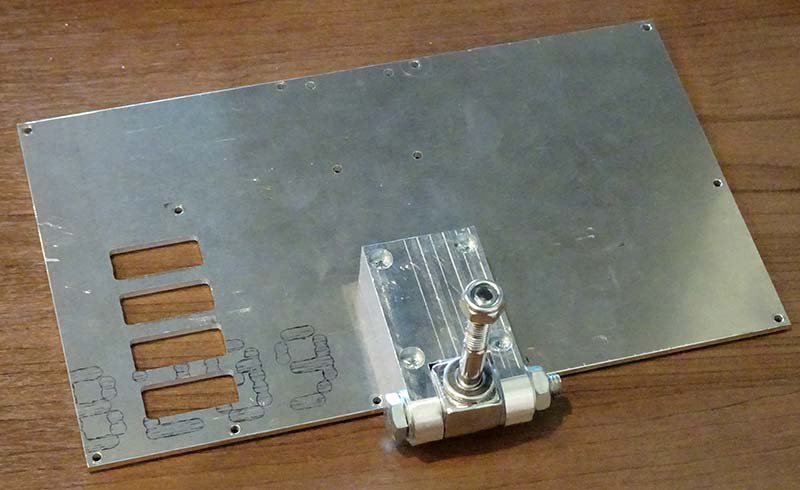
Figure 10 – Back plate is 1/8” aluminum to provide structural support.
The piece sticking up is part of the original Grizzly mount. Ironically, I made these with my CNC mill. The back plate could easily be done on a manual mill and the bracket as well, if you don’t bother with the rounded bottom.
In Figure 11, you see the screen mounted in the bezel, ready for the back plate to be installed.
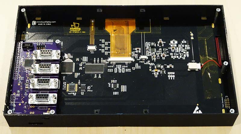
Figure 11 – MCU PCB attached to display electronics, ready for back plate.
Next Time
So far, I’ve tried to give you a good description of the hardware and software that makes up my project.
Next time, I’ll get into details of how to build one yourself and the basics of how to use it. SV
Resources
Project on GitHub
https://github.com/TimPaterson/TouchscreenDigitalReadout
FontGenerator
https://github.com/TimPaterson/FontGenerator-embedded-systems
ScreenDesigner
https://github.com/TimPaterson/ScreenDesigner-for-touchscreens
Article Comments