A Quick Experimenter’s Guide to Servomotors
By Bill Donofrio View In Digital Edition
Servomotors, for the most part, are a joy to work with. They make it possible to precisely control the motion of a motor and are indispensable in robotics, radio control planes, and cars.
If you’ve ever taken one apart, you’ll find it to consist of a gear motor, potentiometer, and control electronics. Figure 1 is an example of a home-built servomotor without the electronics. As you can see, the motor is connected to the potentiometer through a series of gears.
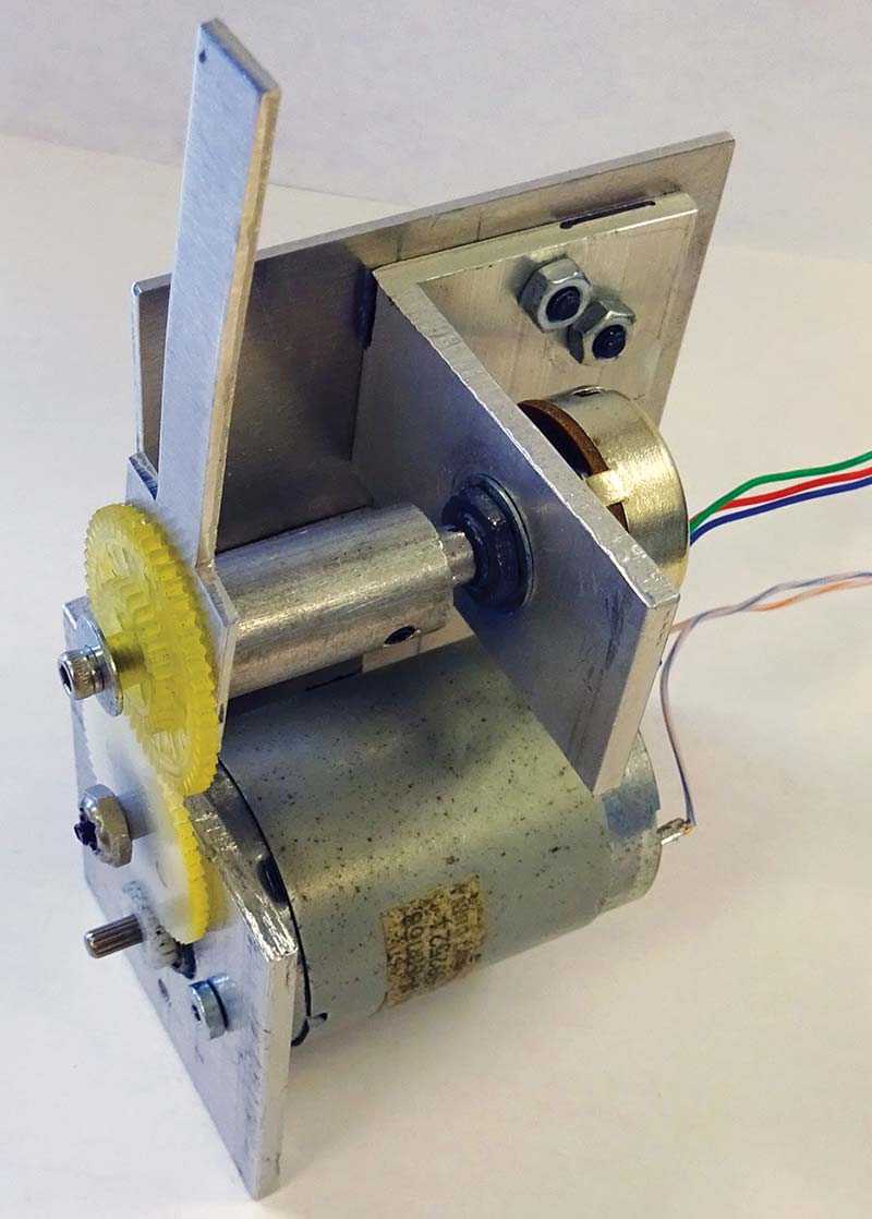
Figure 1.
Small DC motors run very fast, but have very little torque. By adding a reduction gear (small gear on the motor shaft), you increase the rotational force or pulling power of the motor. The potentiometer is used as the sensing transducer to measure the position of the motor.
When the motor moves, so does the wiper arm of the potentiometer. If a voltage is placed across the potentiometer and measured at the wiper arm, it will increase or decrease with the position of the motor.
Build a Joystick Servomotor Controller
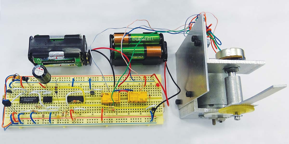
To determine the position of the motor, the control electronics must compare the voltage at the motor potentiometer with that at the position potentiometer as shown in Figure 2.
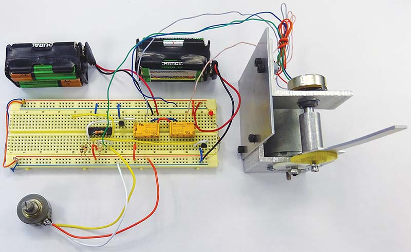

Figure 2.
To measure the two incoming voltages, one comparator is set up in the non-inverting mode and the other in the inverting mode. When the voltages are unequal, one comparator will have a high input and the other low. A high input at either comparator will cause one of the relays to energize.
Since the relay switches are set up in an H configuration, energizing one relay will cause the motor to go clockwise and the other counterclockwise. As you may have noticed, I used a relay H-bridge instead of a MOSFET and separated the power supplies. There are some definite advantages to doing this.
You eliminate motor noise that can cause the circuit to oscillate and, more importantly, you can easily change input voltage up to the specified limit of the relay. This becomes handy when you need to use either a very small motor which runs on low voltage or a large one for torque that requires a higher working voltage.
The larger the voltage differences between the two potentiometers, the farther the motor will rotate. The motor will stop rotation when the voltage at potentiometer P1 equals the voltage at potentiometer P2. In this manner, the motor will track the location of the position potentiometer.
To eliminate the motor from hunting or oscillating — which is caused by the momentum of the motor overshooting the null point (even gear motors can’t stop on a dime) — the two comparators were set up in a window configuration which provides a bit of slop, or a deadband around the null point. Near the null point, both comparators stay low in a specified voltage range, preventing the motor from oscillating.
R2, R3, and P1 provide the window. R3 can be anywhere between 150-330 ohms and is somewhat dependent on your application. By decreasing the value, you will decrease the size of the window and stiffen the motor’s reaction time, though too low a value can cause it to oscillate.
If you add an arm to potentiometer P1, you can make a rudimentary joystick that can manually control a robot arm very effectively. Since there aren’t any mechanical stops and the gear ratio can be optimized for any application, movement from 0 to 360 degrees is possible. Most toy servomotors have mechanical stops at 0 and 180 degrees to prevent damage to the gears.
If you build this circuit and are sure that your wiring is correct but find the circuit doesn’t work properly, reverse the plus and minus leads on the servomotor potentiometer or motor leads. This circuit is polarity sensitive.
The motor potentiometer and the motor must run in the correct direction relative to the input potentiometer. If it doesn’t, the voltage drop across the potentiometer may go up when it should go down or vice versa. The comparator will receive the wrong information and the circuit will work incorrectly, causing the motor to slam the potentiometer into the extreme left or right position.
Parts List for Joystick Servomotor Controller
| C1 | .1 µF | Ceramic Capacitor 10% |
| D1 | 1N914 | General-Purpose Diode |
| D2 | 1N914 | General-Purpose Diode |
| P1 | 5K | Linear Potentiometer Preferred |
| P2 | 5K | Linear Potentiometer Preferred |
| R1 | 10K | 5% Resistor, 1/4 watt |
| R2 | 150-300 ohm | 5% Resistor, 1/4 watt |
| R3 | 5.1K | 5% Resistor, 1/4 watt |
| R4 | 10K | 5% Resistor, 1/4 watt |
| RLY 1 | 5V Coil SPDT | |
| RLY 2 | 5V Coil SPDT | |
| T1 | 2N3904 | NPN Transistor or Equivalent |
| T2 | 2N3904 | NPN Transistor or Equivalent |
| U1 | LM339 | Quad Comparator |
Building the PWM Infrared Transmitter
While this simple circuit is useful, you can go one step farther and control your servomotor with a pulse width modulated (PWM) signal; refer to Figure 3. For a standard hobby servomotor, a 1.5 ms signal with a period of 20 ms moves the servomotor to the center position, while a 1 ms signal moves it 90 degrees from center, and a 2.0 ms signal moves it 90 degrees from center in the other direction. With a 1 to 2 ms signal, 0-180 degrees of movement can be achieved.
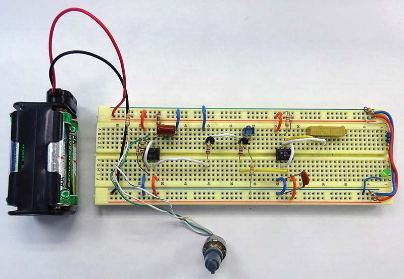
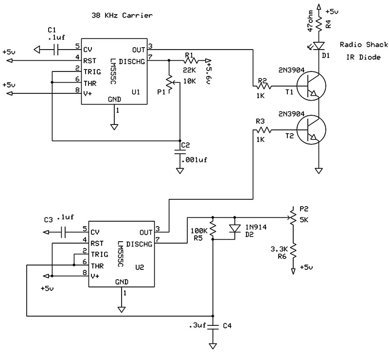
Figure 3.
The transmitter operates by modulating a PWM signal with a 38 kHz carrier. This signal is then demodulated by the infrared receiver module mentioned later in this article.
I used a 555 timer to generate the PWM signal. To do this, the charge and discharge times need to be designed independent of each other. This is made possible by the 1N914 diode. With the diode in parallel with the 100K resistor, capacitor C4 can only be charged through the 3.3K resistor/5K potentiometer combination.
By varying the resistance of the potentiometer, the length of the pulse can be varied from 1 to 2 ms. Since C4 can only be discharged through the 100K resistor, the off time is fixed at approximately 18 ms. By varying the value of C4 from .3 µF to .4 µF you can control the rotation of the servomotor from 90 to 180 degrees.
The output of the PWM is then fed to the 2N3904 transistor and modulated by the other 555 timer configured as an astable multivibrator. To adjust the carrier frequency, turn the 10K potentiometer. To calibrate the carrier frequency, I suggest you use a meter with a frequency counter if you have one.
Parts List Infrared Transmitter
| C1 | .1 µF | Ceramic Capacitor 10% |
| C2 | 001 µF | Ceramic Capacitor 10% |
| C3 | .1 µF | Ceramic Capacitor 10% |
| C4 | .3-.4 µF | Ceramic Capacitor 10% |
| D1 | RadioShack IR Diode as shown online, Vishay TSAL6100 IR Diode, or Equivalent | |
| D2 | 1N914 | General-Purpose Diode |
| P1 | 10K | 15-Turn Potentiometer |
| P2 | 5K | Linear Potentiometer Preferred |
| R1 | 22K | 5% Resistor, 1/4 watt |
| R2 | 1K | 5% Resistor, 1/4 watt |
| R3 | 1K | 5% Resistor, 1/4 watt |
| R4 | 47 ohm | 5% Resistor, 1/4 watt |
| R5 | 100K | 5% Resistor, 1/4 watt |
| R6 | 3.3K | 5% Resistor, 1/4 watt |
| T1 | 2N3904 | NPN Transistor or Equivalent |
| T2 | 2N3904 | NPN Transistor or Equivalent |
| U1 | LM555C | Timer |
| U2 | LM555C | Timer |
Building the Infrared Receiver
The receiver circuit consists of an infrared receiver module that amplifies and demodulates the transmitted signal, and a PWM to voltage converter that feeds the servomotor comparator circuit.
Most any IR receiver module will work; I’ve used discarded TV, VCR, and even IR helicopter modules as long as they can receive a 38 kHz carrier and a continuous signal.
You may also have noticed I used Ni-MH rechargeable batteries to run these circuits instead of alkaline. Alkaline versions have a higher operating voltage which might damage the IR receiver module.
For clarity, I broke up the circuits into parts. After the IR receiver module demodulates the PWM signal, it’s converted to a linear ramp as shown in Figure 4.
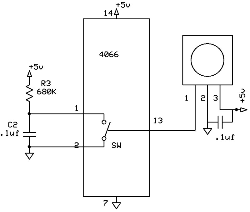
Figure 4: Circuit to convert PWM signal to linear ramp.
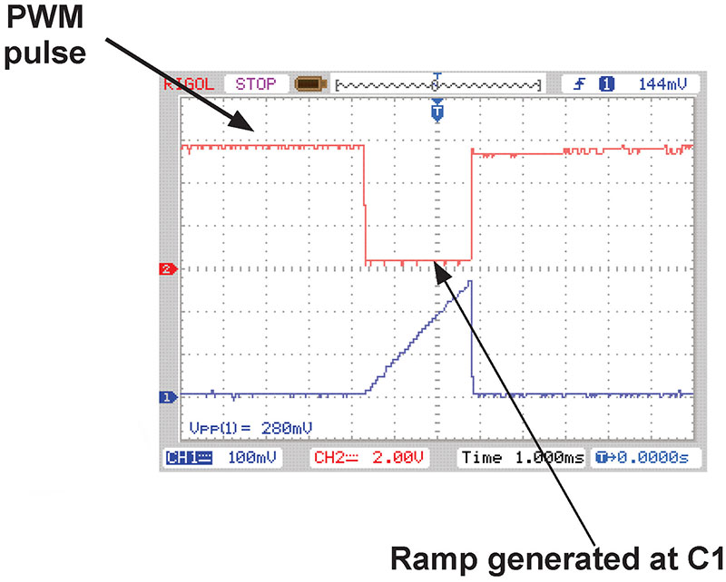
Scope pattern showing the conversion of PWM signal to linear ramp.
A low pulse from the IR receiver to pin 13 of the 4066 Quad Bilateral switch forces it to open, allowing .1 µF capacitor to charge through the 680K resistor, producing a linear ramp.
The longer the pulse, the longer the .1 µF capacitor will charge through the 680K resistor and the higher the voltage across the capacitor. This will continue until the pulse goes high, discharging the capacitor.
A non-inverting amplifier with a gain of 20 amplifies the ramping voltage to a useful level. To convert the ramp to steady DC voltage, the peak voltage must be stored for a short period of time. A ramping voltage would cause the circuit to oscillate.
To do this, a simple sample and hold circuit was used as shown in Figure 5.
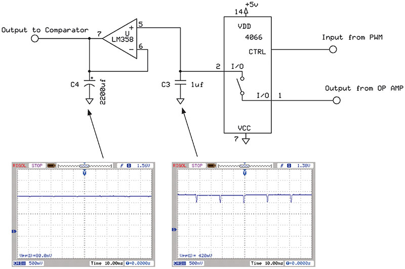
Figure 5: Sample and hold circuit.
A sample and hold circuit is used to catch a brief input voltage and store it until the next sample cycle. The circuit consists of a high impedance op-amp and a CMOS switch. When the switch closes, the capacitor rapidly charges to a new voltage.
Opening the switch captures this voltage and the high impedance of the op-amp keeps this voltage from decaying during 18 to 19 ms between pulses.
To remove the slight spike caused during the charging of C3, capacitor C4 was placed at the output of the op-amp. This produced a relatively smooth DC output that varies proportionally with the width to the PWM input. The conditioned signal is then fed into the servo circuit as described back in Figure 3.
For such a simple circuit (Figure 6), it performed admirably when tested next to a commercial unit. The mechanical aspects of the servomotor were tough and reliable.
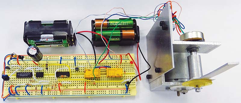
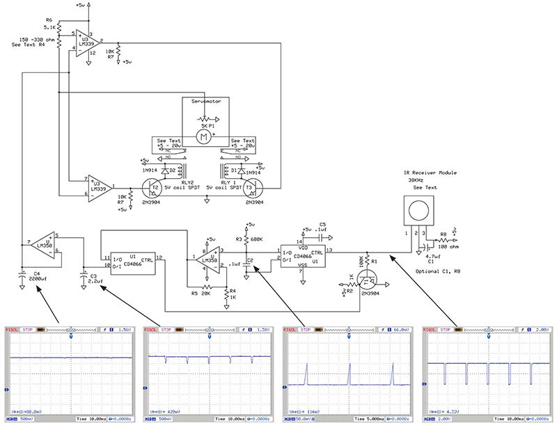
Figure 6: Complete servomotor control circuit.
I hope this article serves you well. SV
Parts List Infrared Receiver
| C1 | 4.7 µF | Electrolytic Capacitor Optional for Noise |
| C2 | .1 µF | Ceramic Capacitor 10% |
| C3 | 2.2 µF | Electrolytic Capacitor |
| C4 | 2200 µF | Electrolytic Capacitor |
| C5 | .1 µF | Ceramic Capacitor 10% |
| D1 | 1N914 | General-Purpose Diode |
| D2 | 1N914 | General-Purpose Diode |
| P1 | 5K | Linear Potentiometer Preferred |
| R1 | 100K | 5% Resistor, 1/4 watt |
| R2 | 1K | 5% Resistor, 1/4 watt |
| R3 | 680K | 5% Resistor, 1/4 watt |
| R4 | 1K | 5% Resistor, 1/4 watt |
| R4 | 150-330 ohm | 5% Resistor, 1/4 watt |
| R5 | 20K | 5% Resistor, 1/4 watt |
| R6 | 5.1K | 5% Resistor, 1/4 watt |
| R7 | 10K | 5% Resistor, 1/4 watt |
| R8 | 100 ohm | 5% Resistor, 1/4 watt; Optional for Noise |
| RLY 2 | 5V Coil SPDT | |
| RLY 1 | 5V Coil SPDT | |
| T1 | 2N3904 | NPN Transistor or Equivalent |
| T2 | 2N3904 | NPN Transistor or Equivalent |
| T3 | 2N3904 | NPN Transistor or Equivalent |
| U | LM358 | JFET Input Dual Op-Amp |
| U1 | CD4066 | Bilateral Switch |
| U3 | LM339 | Single Polarity Quad Comparator |
| IR | RadioShack Receiver Module as shown online, Vishay TSOP4838, Sharp GP1UD26XK, or Equivalent |
Article Comments