A DIY RC Controller and So Much More!
By Steve Koci View In Digital Edition
A dream project of mine has been to create my own DIY RC controller. Using a microcontroller to animate and record character sequences has become the method of choice for the majority of applications. However, sooner or later, you are going to want to have direct control of the operation of a character or prop. Whether it’s to interact with the crowd or to permit you to motorize and provide mobility to a prop, you’ll want to investigate the power RC control offers.
Controlling your completed mechanisms is an important component of a successful build. Like many of my projects, this is a work in progress. This controller provides the freedom to allow you an entirely unique movement while giving you the opportunity to adjust the performance of your character to fit to each individual situation. No two performances are the same!
This system will be included in my next DIY animatronics book. It was meant as a project to add to the soldering chapter that would sharpen soldering proficiency, but also provides a useful tool for the prop builder when completed. As a result of the collaboration with Addicore, the project was ready for release well ahead of schedule.
Although the controller bears my name, this creation and all the accessories were done by Addicore. They are a US-based electronics parts company and wonderful to work with. I hope you’ll check them out for your other electronic needs as well. Shameless plug, they do also carry my first book, The Ultimate Guide To Do It Yourself Animatronics (see Figure 1).
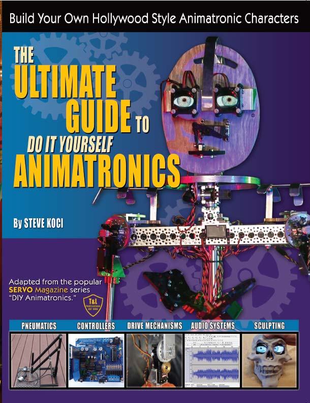
FIGURE 1. The Ultimate Guide to DIY Animatronics, published by SERVO Magazine.
This system will be more than an RC transmitter/receiver system. Finding an easy-to-use and low-cost system that allows you to puppeteer your characters can be a challenge, so I wanted to develop a technique that would introduce builders to this approach of directly controlling characters.
We typically use the process developed by Brian Lincoln which has tremendous flexibility and works well for us. You can find all the details of that system in the December 2016 issue of SERVO Magazine. It has undergone a few changes since then, but still performs flawlessly for the advanced users.
I wanted another choice. I began by searching the Internet for projects developed by others. I soon found that while there are plenty of fantastic projects shared on the Internet, the instructions were often incomplete; parts listed were not correct or were not available at the supplied links; or the code didn’t function properly.
Also, parts are often only available from a handful of different vendors which complicates the process and requires you to pay multiple shipping charges. Parts frequently change and sometimes don’t match those noted in the documentation. Controllers either have to be constructed on a temporary breadboard or you have to order PCBs (printed circuit boards) from a separate vendor. This creates a complicated operation that I wanted to streamline.
Frustrated with this process, I wanted to provide a strategy where all the parts are purchased from the same supplier in a single kit, where the PCBs are included, the tested code worked, and customer support was available if needed.
After a considerable amount of time spent on thought and research, I came up with the idea of designing my own Do-It-Yourself remote controller. It could be used to run a wide variety of robotic and animatronic projects. I teamed up with the knowledgeable folks at Addicore and I believe we have come up with something special! The first version will include two joysticks, two sliders, and a variety of pushbuttons. This will allow the user to set up the controller to fit their specific needs.
The purpose of this project included several requirements. I wanted to possibly teach some new skills and build confidence, as well as provide builders with a controller that included capabilities not currently available on other controllers. Putting something like this together and having it bring a vehicle or character to life is very fulfilling and will hopefully encourage builders to take on even more involved projects. My requirements included the following:
Project Objectives
- A DIY component that includes some soldering.
- A puppeteering controller that can be recorded and separately triggered.
- A live controller for multiple props that can retain the ability to act as a conventional RC controller.
- A device able to control small DC motors with the addition of a motor controller add-on shield.
- A complete RC system which uses the same transmitter to simply switch receiver board types.
- A design which is uncomplicated — no 100 page manual.
- Basic control options only. If more advanced features are required, you might want to examine some of the other fine units out there.
In the initial configuration, you’ll have a highly functional and useful addition to your controller collection. However, the best is still to come. The plans for Version 2 include the ability to puppeteer your character using the controller and storing the program on the receiver board via an SD card. This board will then be able to be triggered and run your program independent of the transmitter.
You’ll now have an easily programmed, stand-alone puppeteering board! This feature takes the controller beyond those currently available for this limited amount of investment. Watch the website for its release and pricing.
Let’s Build a Project
This project will require that you are already comfortable with soldering equipment and techniques. Putting this kit together will allow you to put those skills into practice.
The complete Version 1 kit can be purchased from the SERVO/Nuts & Volts webstore (see Figure 2). It includes the transmitter PCBs and all the necessary components to populate them. It also comes with an assembled receiver, as well as a servo and connector cable to test your controller when you complete the build.
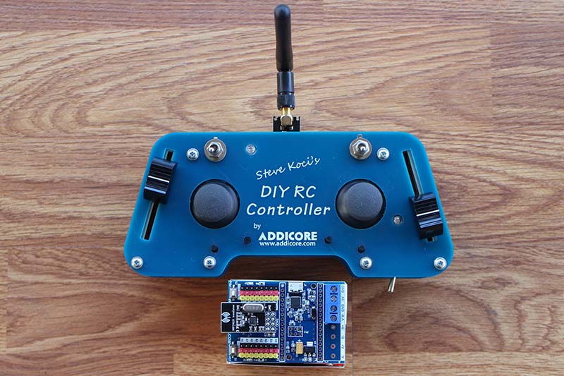
FIGURE 2. The assembled transmitter and receiver.
The software uses the readily-available Arduino IDE (integrated development environment) with links provided to the complete software package. The cost of the complete kit at the time of this printing is $56.95 (see Resources).
Transmitter Assembly
This RC controller system includes three major components: the transmitter; the receiver; and the NRF24L01 wireless transceiver modules. In this kit, the receiver and NRF24L01 with the onboard antenna come fully assembled with any necessary code preloaded. Assembling the transmitter will require some soldering but should be well within the capabilities of anyone with basic skills as mentioned (see Resources).
The transmitter can be purchased already assembled for an additional $20 from Addicore for anyone without the soldering skills or those not interested in doing the assembly themselves.
The kit comes with all the required parts (see Figure 3). Also included is a complete set of build instructions so I won’t detail the construction here. This is simply a brief overview.
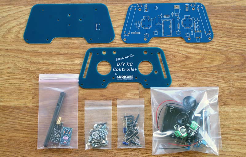
FIGURE 3. Everything you need is included in the kit.
The transmitter assembly is made up of three separate boards. They’re designed more like a game controller than the traditional RC controller. The idea was that more people would feel comfortable using this form factor as most people have used them before.
- The cover board has the actual slides, switches, and the two joystick controls.
- The interior board is where all the soldered components are installed.
- The battery box is attached to the bottom board and utilizes four AA batteries. This means there is no additional charger which simplifies providing power to the transmitter.
The three boards are attached together with standoffs. This arrangement allows the board to be as thin as possible, making it more comfortable to use (see Figure 4).
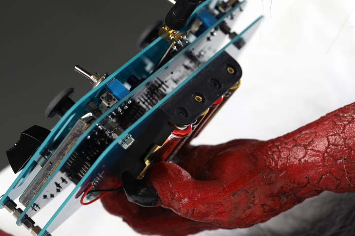
FIGURE 4. The use of multiple boards makes it easy to hold.
The controller microcontroller does have the basic code preloaded and tested, but the code is also provided for those that want to customize it to fit their needs. This is the link to the controller code: https://github.com/addicore/Steve-Koci-s-DIY-RC-Controller and this is the link to the receiver code: https://github.com/addicore/Boffintronics-RC-Receiver. All code is GNU General Public License v3.0, allowing each user to modify and adapt the code to fit their needs.
Within the code, there are several variables that can be easily adjusted:
- Servo end limits can be set.
- Servo movement direction can be reversed.
- Servo dead zone can be adjusted.
Up to four props can be controlled by installing a separate receiver board in each one. They currently run $12.50 from Addicore. You can then toggle between each board by use of the two switches. This feature is especially useful for those whose patrons move between a number of props. You can have full control to activate and manipulate each prop as needed.
The controller code is written to use any one of 10 frequencies. The end user can program which frequency the boards will utilize while in the field. No need to make these adjustments while connected to a computer. You can also switch between individual receiver mode or multi-board mode.
The current configuration of the RC transmitter and receiver combo will control up to six servos simultaneously along with six digital outputs.
The addition of two slide switches is something that I had always wanted in a controller. Being able to precisely set the position of your servo is a feature that is extremely helpful when puppeteering your characters. The visual reference that shows the exact location of the servo by checking the slide position is very handy.
The controller also includes a variety of buttons that can be utilized for other purposes. An example would be to add LED lights to your RC car that could be remotely turned on and off.
Two different antenna choices are available on the NRF24L01 wireless module. If you require greater range, you can use the external antenna model, or if you want something more compact, use the version with the onboard antenna (see Figure 5). The second version is probably sufficient for our prop control purposes, but you may want the external antenna model if, for example, you are using it to control an RC car.
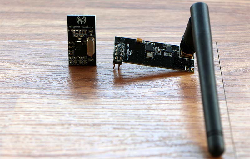
FIGURE 5. The NRF24L01 comes in two versions.
Putting It to Work
Now that we have this new controller up and running, it needs to be put to use. I have a variety of projects in need of something like this, but I chose to bring a character to life that has been patiently waiting his turn.
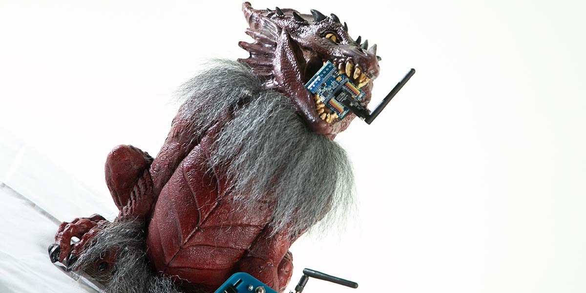
I have always wanted an animated dragon. I picked up this particular dragon while doing research online (see Figure 6). Okay, I was simply surfing the Internet, but that is often when I come upon some of the coolest items.
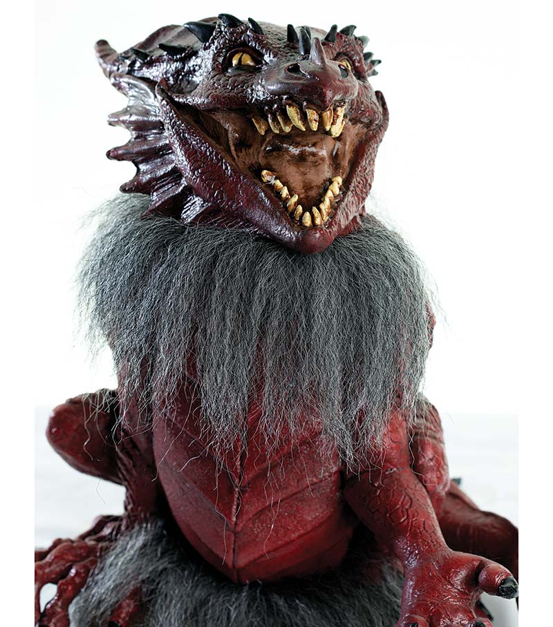
FIGURE 6. This dragon puppet makes a great animatronic starting point.
It has a poseable tail and the head is separate from the body (see Resources). He seems to be currently out of stock as I have not been able to find him available again from any of the vendors I had researched when I purchased mine. A good reminder to buy things when you see them as they may be gone the next time you search!
I used four Hitec servos from ServoCity to provide motion to the dragon (see Resources): one to move the hand; a second servo to manipulate the tail; the third allows the head to rotate side to side; and the final servo articulates the mouth (see Figure 7 and Figure 8). Since I’m only using four servos, I’m able to control them all with the two joysticks. This makes puppeteering a breeze!
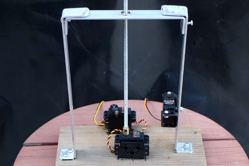
FIGURE 7. Body interior servo layout.
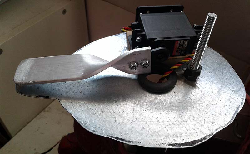
FIGURE 8. Head mount with the jaw servo.
Wait! You say that you have no servo projects on the workbench that require an RC controller right now? No worries! The controller can be used to run one of Addicore’s simple-to-assemble Sumo bots (see Figure 9). This kit comes with its own receiver board that operates using an app on your phone (see Resources). I find it much easier to drive using the RC controller.
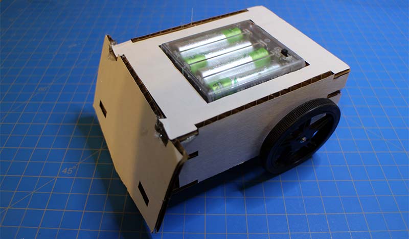
FIGURE 9. The easy-to-build Sumo bot.
This is a quick and easy build that will allow you to test out your new controller and have some fun as well. The Sumo bot is an easy-to-assemble vehicle that only requires the use of a glue gun. It’s also a great project to share with the kids which will help boost their enthusiasm for working with robots. Currently, it’s priced at $37.50. Watch Addicore’s website for the release of the code.
The Best Is Yet To Come
This is just the beginning. There are several new models in the pipeline including:
- A shield that’s in the works will include its own motor driver board allowing you to control small DC motors. This shield will attach directly to the receiver board with the addition of two header rows. You’ll also need to install a couple of extra terminal blocks (see Figure 10). This board and code should be available on the website soon after this goes to press as well.
- A 3D printed case. We’d like to design a 3D printed case for this unless someone beats us to it. If you design one, please share it with the community so others can benefit.
- A transmitter board with write on tabs on the cover board. This allows the user to add their own switch descriptions with a Sharpie™ marker; being able to customize the controller to fit each specific application. Anything that helps me remember the layout is helpful! These will be erasable with a little alcohol, so you can alter your transmitter layout. In the meantime, you can use a Silver Sharpie on the top board now and it will still be removable.
- A puppeteering system that is stand-alone and triggerable. It can use multiple receiver boards with the programming stored in non-volatile memory. The soon-to-be-released version will allow you to record a sequence with up to six servos which can be recorded and played back when triggered. This will require a different receiver board than the one used in the Version 1 model. This new board will include onboard storage in the form of a microSD card. We also plan on new programming that will provide for multiple sequences to be recorded and played back. This will allow for some variety in the playback, as well as provide the option for a static track between activations of the primary programming.
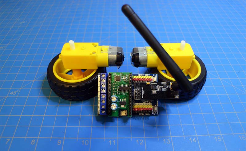
FIGURE 10. The motor driver shield is perfect for small DC motors.
The purpose of this controller was to come up with something that is easy to use and more appropriate for someone interested in their first puppeteering project. I also wanted it to retain all the basic functions of a standard RC controller. Thanks to the fine work of Alex and Andre at Addicore, I believe we have not only met those requirements, but exceeded them.
I’m excited for the upcoming upgrades to the controller and am looking forward to seeing how you integrate it into your own projects. SV
Resources
Full Controller Kit
https://store.nutsvolts.com
Receiver Board
www.addicore.com/boffintronicsrcreceiver
Dragon
https://amzn.to/36bQ5NZ
ServoCity
http://bit.ly/2OCMbpd
Sumo Bot
https://www.addicore.com/CardboardSumoBot-p/ad494.htm
Article Comments