Ways to Move Your Robot
By Gordon McComb View In Digital Edition
All mobile robots move. That's what makes them mobile, after all. Wheels, tracks, and legs are the most common ways to propel a robot across the floor. Which one should you use? That can be a tough question. Selecting the right system starts with figuring out what you want your robot to do.
It also requires giving a very close look at the mechanical requirements of building the drive system of your bot. It’s all too easy to go overboard and plan a drive system that’s too complex or expensive to build. In this article, I’ll review the three main locomotion systems for desktop robots, and things to keep in mind when deciding which one is right for your next mechanical creation.
Using Wheels
Wheels are the most common way to move a bot. For wheeled robots, their drive geometry is defined by how each one is steered. There are a lot of choices. The most common way to move a robot is with differential steering.
The most basic form consists of two wheels mounted on either side of the robot as shown in Figure 1.
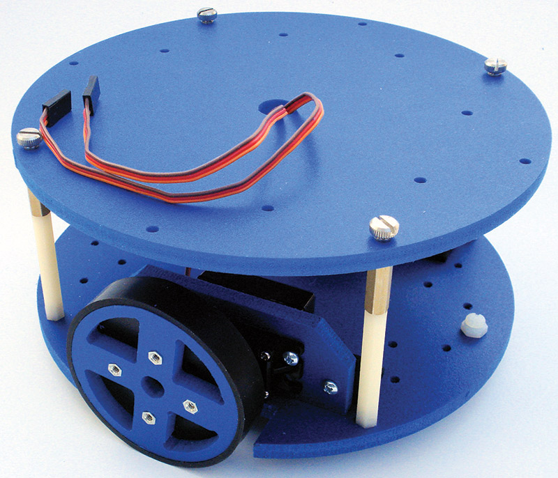
FIGURE 1. Differential steering involves using two motors on either side of the robot. The robot steers by changing the speed and direction of each motor.
It’s called differential steering because the robot is steered by changing the speed and direction (“difference”) between these two wheels. One of the key benefits of differential steering is that the robot can spin in place by reversing one wheel relative to the other.
A feature of most differentially-steered robots is that they use one or two casters (or skids) placed center-line over the robot in the front and/or back to provide balancing support for the base.
In dual caster/skid designs, the wheels are placed in the center of the vehicle and a separate caster on each end (see Figure 2).
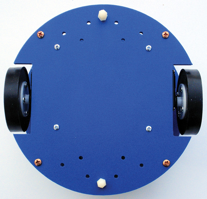
FIGURE 2. Two casters (or skids) are needed on differentially-steered robots with motors in the center. This provides maximum balance and support, but reduces the robot's ability to navigate rough terrain.
This arrangement provides maximum stability, but requires a relatively flat traveling surface. On rough terrain, the casters may cause the drive wheels to lose contact with the ground.
In single caster/skid designs, the wheels are placed on one side of the vehicle, and a caster on the other. This has the benefit of creating a good three-point balance without causing as much of a problem on rough ground. The disadvantage is that the robot’s turning radius isn’t as tight as it is when the wheels are mounted in the center.
Variations of the two-wheeled base include four or six wheels (4WD, 6WD). On bases that use more than two wheels, support casters or skids aren’t generally needed.
In 4WD and 6WD systems, each wheel can be powered by a separate motor. The motors on each side are operated as if they were one unit; all the motors on the left turn on or off at the same time, for example. Figure 3 shows a 4WD robot base that uses four motors, each connected to its own wheel. The wheels are pulled from an inexpensive toy. Their hard plastic construction reduces “skittering” caused by friction in turns — a problem with four- and six-wheel drive designs.
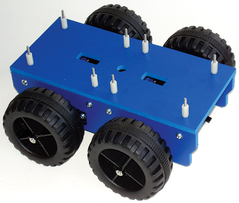
FIGURE 3. Four- and six-wheel drive robots use multiple wheels to provide traction and stability. The wheels on each side of the robot may be individually driven by separate motors, or driven through linkages or gears by a central motor.
Cost and weight can be reduced by using just a single motor to power one wheel on each side, letting the other(s) rotate freely. Or, the wheels on each side can be connected to the motor by way of gears or belts. This is harder (and more expensive) to implement, but it can provide better traction over uneven road than by using freely rotating wheels.
The wheel size greatly influences the traveling speed of the robot. Larger wheels (for a given motor RPM) make the robot go faster. Example: If the robot travels at six inches per second with 1.5” diameter wheels, changing to 3” wheels increases speed to 12 inches per second. The speed increase isn’t without cost, however. Torque is reduced as the wheels get bigger.
A main benefit of wheels is that they make measuring distance — called odometry — very easy. Sensors are mounted on the wheels which detect even incremental rotation. By comparing the motion of the wheels on each side, it’s possible to keep the robot on a straight path. Odometry can be used to control speed, as well as measure distance. Accurate travel distance calculations are much more difficult with tracked and legged robots.
While differential steering is the most common drive geometry for robots with wheels, there are other approaches. One uses a single drive motor powering two rear wheels and a steering wheel in the front; the arrangement is just like a child’s tricycle (see Figure 4).
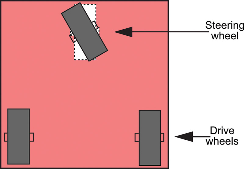
FIGURE 4. In tricycle steering, one drive motor powers the robot; a single wheel in front steers the robot. Beware of short wheelbases as this can introduce tipping when the robot turns.
On these designs, be careful of the wheel base of the robot — the distance from the back wheels to the front steering wheel. A short base will cause instability in turns, causing the robot to tip over in the direction of the turn.
Tricycle-steered robots require a very accurate steering motor in the front. The motor must be able to position the front wheel with sub-degree accuracy. Otherwise, there is no guarantee the robot will be able to travel a straight line. Most often, the steering wheel is controlled by a servo motor.
There are two basic variations of tricycle drives:
- Unpowered steered wheel. The steering wheel pivots but is not powered. Drive for the robot is provided by one or two rear wheels.
- Powered steered wheel. The steering wheel is also powered. The two other wheels only rotate freely.
Other forms of steering with wheels includes car-type (also called Ackerman), tricycle, and omnidirectional. Space doesn’t allow describing each in details. Do a Web search if you’d like to learn more about these other methods.
Using Tracks
Since World War I, the tank has become the symbol of military battles. Little wonder that the tank design is popular among robot builders. The same principles that make a military tank superior for uneven terrain apply to robots. Tracks or treads form a wide base that enhances stability of the vehicle. The mechanics of the treads create a “virtual” wheel with a very large surface area that contacts the ground.
Like the common two-wheeled bot, tracked robots are also differentially steered. Two long chain-like tracks (or treads) are mounted parallel to each side of the vehicle like that in Figure 5. A separate motor powers each track in either direction via a sprocket; the toothed design of the sprocket ensures that the drive mechanism doesn’t just spin if the track gets jammed.
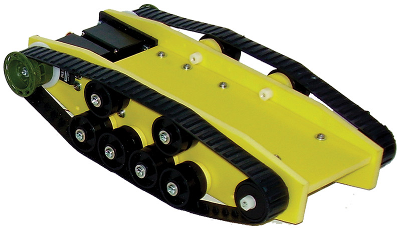
FIGURE 5. Robots with tank tracks (also called treads) can be used over rough ground.
Though there are some hybrid vehicles that use tracks in addition to wheels, typical tank locomotion is provided solely by the two tracks. The tracks are kept inline by the use of unpowered idler rollers placed at intervals along the sides of the vehicle.
Tracks turn by skidding or slipping, and they are best used on surfaces such as low nap carpet or dirt that readily allow low friction steering. When using treads, try to pick a relatively low friction material. Very soft rubber treads will not steer well on smooth surfaces.
No matter what the track material, it’s always best to steer by reversing the tread directions — don’t just stop one of the tracks. This will reduce the friction, and allow for easier turns.
If both tracks move in the same direction, the robot is propelled in a straight line forward or backward. If one track is reversed, the robot turns (Figure 6).
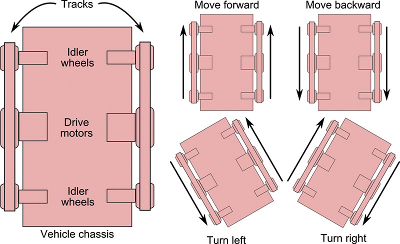
FIGURE 6. Like differentially-steered wheeled robots, tracked bots steer by changing the direction of the treads.
This method is often referred to as tank steering or skid steering, but at the end of the day it’s the same as differential steering.
Because of the long length of the track, tank bots don’t need a support caster or skid. The track acts as one giant wheel, one on each side.
The main benefit of a tracked vehicle is its ability to navigate over rough terrain. The tracks enhance the “grip of the road” allowing the robot to travel over loose dirt, sand, grass, and other surfaces that a wheeled robot can only dream about. The large surface area of treads greatly increases friction. A tracked vehicle can have trouble making turns, and the treads can pop off if they are made of flexible rubber. Suitable tread material can be hard to find.
A common approach is to either use the Tamiya rubber Track and Wheel set (Tamiya #70100), or else hack a toy tank like the one in Figure 7.

FIGURE 7. A handy source for robot tracks is motorized tank toys.
You can keep the tracks and all its sprockets and wheels on the original toy, or transfer them to body pieces you’ve specially made for your robot like that in Figure 8.
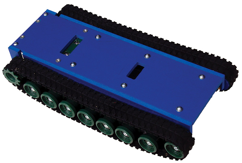
FIGURE 8. The running gear of a hacked tank toy may be removed and placed on your own chassis. This involves more work, but provides greater flexibility in designing your robot.
Another problem is that rubber treads can stretch over time. A track tensioner mechanism is recommended. A simple tensioning technique is to make one of the free-wheeling idlers adjustable. The axle for the idler is inserted in a slot rather than a hole. Fastener hardware keeps the idler locked in place over the slot. As the tracks stretch, you can move the idler to keep proper tension.
A better way to prevent loose and sloppy tracks is to use material that’s not stretchy. Figure 9 shows the drive mechanics of a homebrew tracked robot that uses plastic tread links.
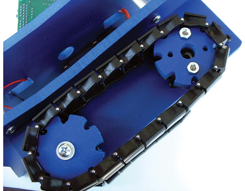
FIGURE 9. Unlike the common rubber treads used in tracked robots, plastic track links resist stretching, so they won't pop off as easily when the bot makes a turn.
Each link is separately molded out of rigid plastic; a stainless steel rod connects the links. You can add or remove links to adjust the length of the tread. These particular links are available from online stores. Look for other sources for hard plastic (and in some cases, metal) tank treads.
Using Legs
Why roll when you can walk? That’s the idea behind robots with legs. Walking bots may have two, four, six, and even eight legs — the six leg (hexapod) variety is perhaps the most common. Four or more legs provide what’s known as static balance, where at least three appendages touch the ground at any time. With this arrangement, the legs prevent the robot from toppling over.
Joints of each leg are defined as degrees of freedom (DOF): the more DOF, the more agile the platform but the more difficult it is to build. Two or three joints is typical for four-, six-, and eight-legged robots. In most designs, each joint requires its own motor, so for each DOF the cost, weight, and complexity of the robot quickly escalates.
A 3DOF hexapod, for example, requires 18 motors — three motors found in each of its six legs. Most walking robots use servo motors from model radio control airplanes. At an average cost of $12 per motor, that’s $216 for just the motors. (To be fair, you’re better off with higher quality servos for your walking bot. It’s not hard to spend $300 to $500 on just the motors for a well-equipped hexapod robot.)
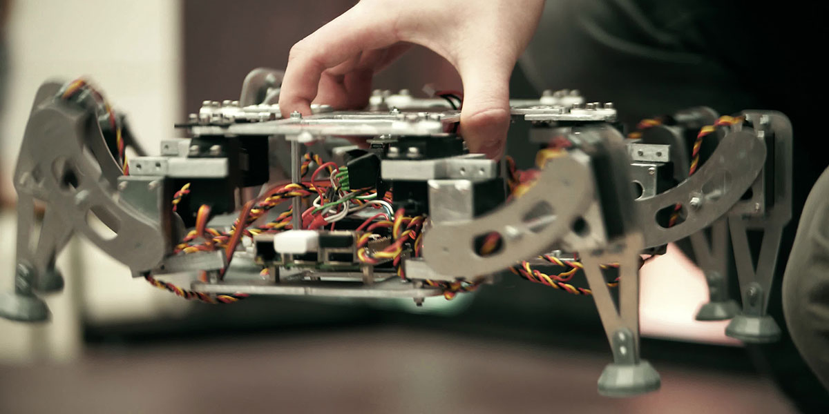
Of all locomotion types, legs require the greatest degree of machining and assembly skill. Flexing of legs can cause stress in material; acrylic plastics can break over time. Figure 10 shows a 2DOF hexapod constructed out of expanded PVC plastic. The better walking bots use aluminum metal, polycarbonate plastic, or ABS plastic.
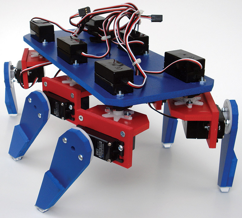
FIGURE 10. Multiple RC servo motors act as leg joints in a walking robot. This design uses 12 motors total; two servos for each of its six legs.
The gait of a walking robot refers to the pattern of its leg movements. Gaits can and do differ depending on the speed of travel — a running gait is completely different from a walking gait, for instance.
Figure 11 shows the most common gait of a six-legged robot. This gait is often referred to as an “alternating tripod gait” because at least three legs are always touching the ground at the same time, providing the static balance noted earlier.
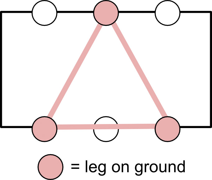
FIGURE 11. The way a legged robot walks is its gait. Typically, on a robot with six legs (hexapod), three legs touch the ground at any one time in the form of a tripod, providing static balance.
The alternating tripod gait goes through a number of sequences. For each side of the tripod, the legs are lifted, lowered, and swept forwards or backwards in unison. This provides for a reasonably fast walk while still maintaining good static balance as the weight of the robot is shifted from one side to the other.
Legs act either to lift or to power (see Figure 12).

FIGURE 12. Like any walking creature, a legged robot moves by lifting a leg segment up and down while sweeping the leg back and forth.
Legs are lifted to orient them into a new position. During lift, the leg does not provide propulsion, nor does it contribute to the balance of the robot. Legs that power, propel the robot in the opposite direction of the movement.
Because of the complexities of constructing legged robots, most bot builders instead opt to purchase a kit of premade parts.
So, now you have the basics of making your mobile robot, well, mobile. For your next project, be sure to carefully consider the pros and cons of each drive method. Be sure to match the drive system to your budget, construction skills, and robot play area. There’s nothing worse than to see a helpless robot designed for rolling over carpet get caught in the soft sand of your back yard. Talk about cruel! SV
Gordon McComb is the author of the best-selling Robot Builder’s Bonanza and Arduino Robot Bonanza, both published by McGraw-Hill.
Article Comments