All About PIC Pulse Width Modulation
By Thomas Henry View In Digital Edition
Pulse width modulation (PWM) is a method by which the on-time of a rectangular waveform is shortened or stretched. It's a valuable technique with many applications, such as efficiently controlling the speed of a DC motor or the brightness of lamps and LEDs. In the realm of audio, it might be employed to approximate analog waveforms by means of filtered pulse width modulated signals. It even shows up in the transmission of coded messages from outboard sensors to control circuitry, for example.
Microcontrollers and PWM make a perfect couple. Of course, PWM can always be created in software just by toggling a port pin on and off at appropriate moments, but that takes an awful lot of babysitting just to get the job done. A better approach is to select a microcontroller sporting an internal hardware module capable of generating PWM independently. Most — if not all — of the PIC microcontrollers contain at least one PWM module which can be turned on and left to do its thing without any further intervention.
The huge datasheets for the PICs present a wealth of information on how to coerce the module into creating a pulse width modulated signal. There are several stumbling blocks to slow the newcomer down, unfortunately.
First, the datasheets are rather terse, and almost never organized in a friendly or pedagogically sound format. Wouldn’t it be more rewarding to start with the big ideas first supplying the details later, only when they’re truly needed and make more sense?
Another problem specific to PWM is that all of the information in the typical PIC datasheet is phrased in terms of period (time, measured in seconds) rather than the more useful notion of frequency. Lastly, beginners sometimes trip over the algebra (elementary as it may seem) needed for putting the various formulas to good use.
So, in this article, I’ve rearranged the ideas to be much more approachable, reworked everything naturally in terms of frequency, and have taken care of all the necessary mathematical finagling. By the time you conclude with the lab demonstrations at the end, you should be all set to start using pulse width modulation in your own robotic designs.
First Steps
To keep things concrete, I’ve focused specifically on the common and inexpensive PIC16F88, but the ideas are similar for other PICs. Let’s get some language down first. Refer to Figure 1 which shows a representation of a rectangular waveform.
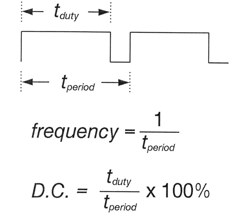
Figure 1.
The total time required for one complete cycle is called the period, typically measured in seconds.
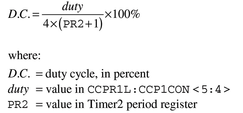
The on-time is referred to as the duty — again a measurement of time. It’s handier to express this as a duty cycle (DC) in percentage, as the figure indicates.
Within the PIC is a device called the CCP module, which stands for Capture/Compare/PWM. It can be pressed into service in several different ways, but for now all we need to know is that it forms the heart of the PWM machinery. Also within the PIC is Timer2, which is really nothing more than a counter chugging away independently of the remaining microcontroller innards.
Looking back at Figure 1, Timer2 counts away and when a certain number is hit, the output pulse drops low completing the duty portion. The timer keeps incrementing and eventually hits a second number signaling that the output port pin should go high again, thus concluding the period. And so it goes forever, or at least until Timer2 is shut off.
So, what about that port pin? Well, here’s the first thing you need to know. Thanks to the magic of multiplexing, the PIC16F88 allows you to select which of two pins (B.0 or B.3) should actually output the pulses. Whichever is chosen, it will then be known as CCP1. This is determined by the CONFIG1 configuration word established when the microcontroller is programmed. You’ll see how to set this in the software demonstrations coming up shortly.
The second thing you have to take care of is making sure whichever port pin you selected is enabled for output. Going by a rather awkward name, TRISB is the register that takes care of this. Again, the demonstrations should make it clear what’s needed.
The Required Registers
As a grand overview, starting up the pulse width modulator requires little more than plugging a number in to set the frequency, and another number to set the duty cycle. Figure 2 illustrates the specifics.
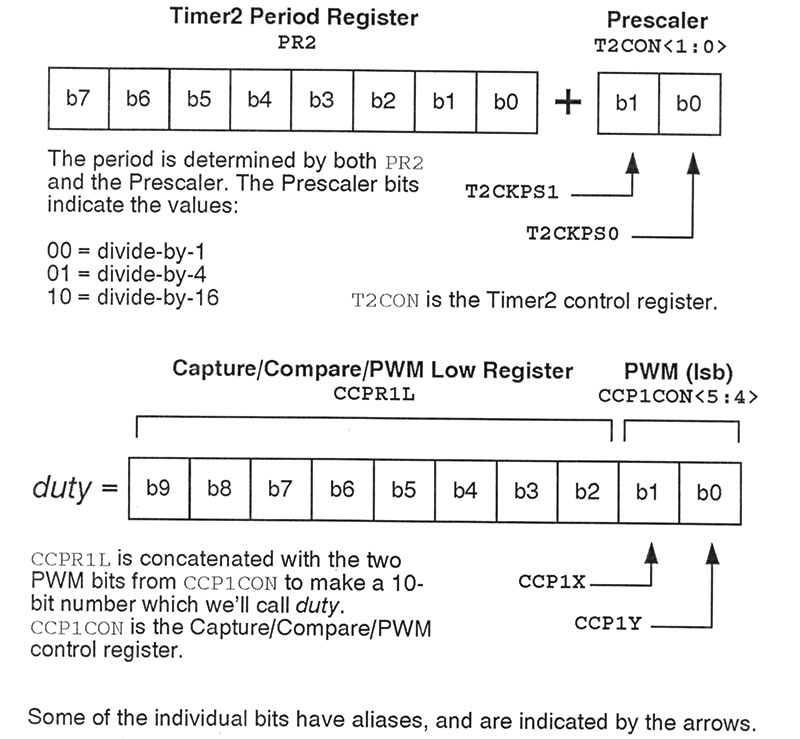
Figure 2.
The duty cycle is the simpler of the two, so let’s start there. A 10-bit number — which we’ll dub duty — determines the duty cycle. This is split into two parts, with the eight most significant bits going into the CCPR1L register of the PIC, and the remaining two lower order bits plopped into bits 5 and 4 of the CCP1CON register. A compact way of indicating this is as CCPR1L:CCP1CON<5:4>.
The period is also represented as a 10-bit number. In this case, the eight most significant bits go into register PR2, which stands for Timer2 Period Register. The lower two bits are actually a code, representing a prescaler value. Before moving on, take a moment to study Figure 2 which pretty much pulls the details together in one place.
How to Choose Your Numbers
So, we now know that two 10-bit numbers are needed to set the frequency and the duty cycle. The question is, what numbers?
Formula 1 tells us all about the first number.
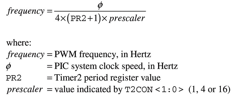
Formula 1.
I’ve converted this from the PIC datasheet to deal in frequency instead of period. Rather than restating the obvious, I’ll ask you simply to scan over the formula, looking at the units and familiarizing yourself with the variables. Likewise, spend a few moments with Formula 2 which tells us all about the duty cycle.
Formula 2.
With a bit of elementary algebra, Formula 1 becomes that of Formula 3.
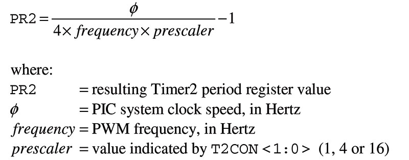
Formula 3.
Rearranged thus, we can rapidly compute the numbers required to set the frequency of the PWM waveform. In particular, begin with a prescaler value of one, then plug in the PIC system clock frequency and the desired PWM frequency. After a few punches on the calculator keyboard, you’ll end up with that number PR2 mentioned above.
Remember, this is supposed to be an eight-bit number, so if it exceeds 255 in value, you’ll then try a prescaler of four and recompute. If it’s still too big, then go back to the drawing board and see what happens when the prescaler is 16. If the final result remains greater than 255, then you’re asking the PIC for the impossible and will need to rethink things.
In case it isn’t clear, in all of these formulas we’re talking integer arithmetic. So, round any fractional result to the nearest whole number. Assuming things went well, at this point you’ll have values for PR2 and the prescaler.
Formula 4 is a reshuffled version of Formula 2.
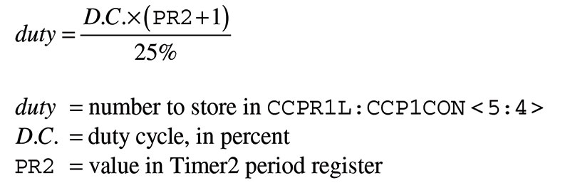
Formula 4.
Just plug in PR2 and the desired duty cycle (in percent), and away you go! You’ll now have that number we decided to call duty.
A Sample Calculation
I promised to make this easy, and the best way to convince you of that is by example. So, get out your calculator and let’s see what happens.
For the sake of argument, let’s suppose we’re running the PIC16F88 on its own internal 8 MHz system clock. Further imagine that we desire a 10 kHz pulse wave set to a 75% duty cycle.
Returning to Formula 3, let’s try a prescaler value of one. Plugging in the numbers and cranking away yields a PR2 result of 199, which can indeed be represented as an eight-bit number. Then, computing with Formula 4, we see that the number for duty should be 600. We have everything we need.
Incidentally, the numbers turned out perfectly here, but you won’t always be able to hit the frequency or duty cycle smack-dab on the button.
Here are a couple niceties not given specifically in the datasheet, yet easily derived nonetheless. If you put the value for PR2 into Formula 5, you can then predict the largest usable pulse width number.
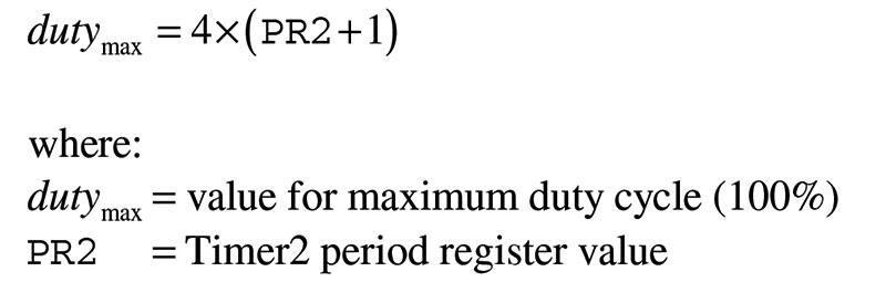
Formula 5.
I get 800 for our example above, and so should you. Thus, the possible duty cycle numbers may range from zero (corresponding to 0%, of course) all the way up to 800 (representing 100%). Any number larger than this simply keeps the output pinned at full on.
Formula 6 will tell you what the increments are.
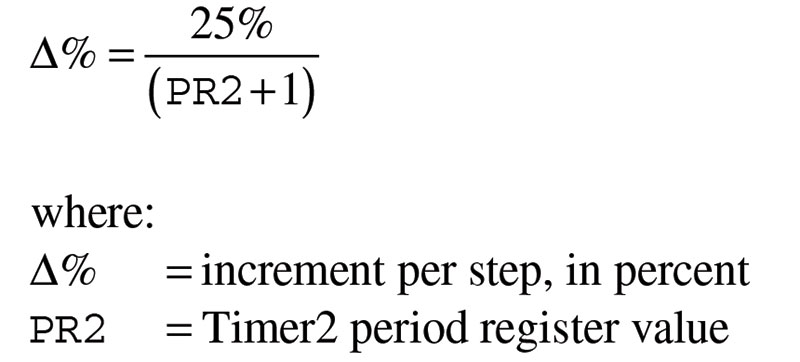
Formula 6.
Staying with our example, then, we see that each change from zero to one to two on up to 799 to 800 corresponds to an increment of 0.125% — a very fine division indeed.
Finally, the computation described in Formula 7 will tell you what sort of resolution to expect for your choice of frequency.
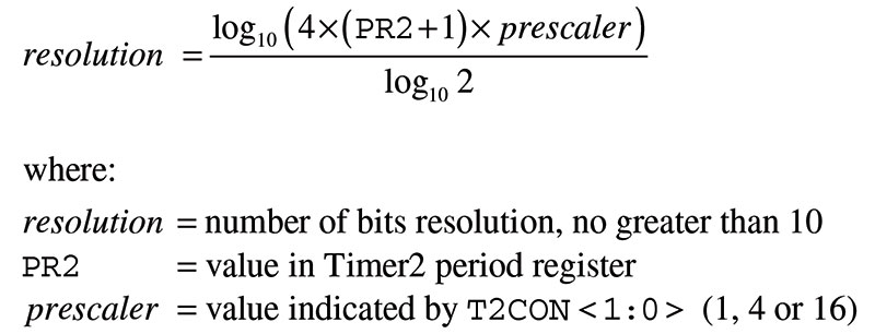
Formula 7.
We just saw in our example that the highest allowable number is 800, so pretty clearly this will lend a resolution of 10 bits. (It takes a 10-bit number to represent 800, the top value).
Let’s check this against Formula 7. My calculator shows about 9.64, which rounds up to 10 as expected. For certain frequencies, you may wind up with lesser resolution, but remember it can never be greater than 10.
If mathematics isn’t your cup of tea, don’t let that logarithm in Formula 7 rile you. In the final analysis, logarithms are really not much more than digit counters.
Pulling It All Together
Throughout my years in the classroom, I’ve always followed the “forest for the trees” model when teaching. You should have the forest plainly in view now and are finally ready to see the trees up close and personal.
Here goes with a detailed step-by-step procedure for cranking out PWM on a PIC.
- Decide on your desired frequency and duty cycle.
- With a prescaler of one, compute PR2 using Formula 3. If the result is out of bounds (larger than 255), repeat again with a prescaler of four, and if still needed, then try 16.
- Compute the value of duty using Formula 4.
- If desired, compute the maximum duty number, the percent change, and the resolution, using Formulas 5, 6, and 7, respectively.
- Specify which CCP1 pin to use in the CONFIG1 configuration word.
- Store the value of Step 2 in the register PR2.
- Store the value of Step 3 in CCPR1L:CCPCON<5:4>.
- Make the CCP1 pin an output by means of the TRISB register.
- Load the prescaler value code into T2CON<1:0>. The codes are given in Figure 2.
- Enable Timer2 by setting T2CON<2>.
- Indicate PWM mode to the Capture/Compare/PWM module by setting both bits of CCP1CON<3:2>.
This may look like a lot of work, but do it once or twice and it becomes second nature. It’s probably obvious, but a programmable calculator or spreadsheet can lessen the tedium.
To conclude your PWM education, be sure to get the four demonstrations available in the downloads. These are written in the free open source language Great Cow Basic, and are heavily documented and commented throughout.
Begin by studying the code to see how the steps described above have been implemented. Finish off by running the demos at the workbench, confirming your expectations.
If you’d simply like to try something practical and colorful, skip ahead to the fourth demonstration which shows how to pulse a bicolor LED from red to orange to green and back again. Figure 3 shows how simple the circuit is; PWM takes care of everything else!
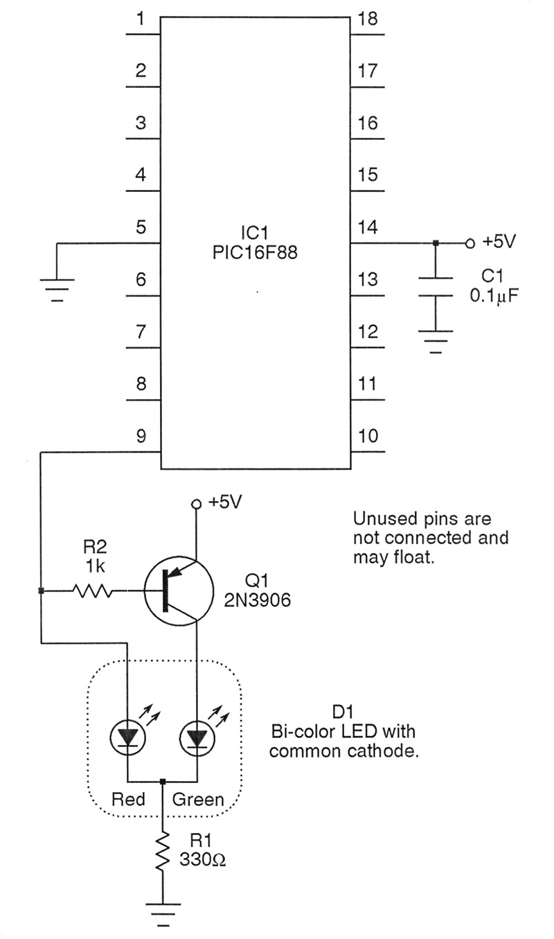
Figure 3.
So, don’t let that datasheet baffle you anymore. Using the straightforward approach described here, you should now be ready to tackle your next robot project involving pulse width modulation! SV
Article Comments