Animatronics for the Do-It-Yourselfer
By Steve Koci View In Digital Edition
Quality animatronics have long been the domain of well staffed, professional prop shops. However, with the considerable progress and improvements, and the many new products currently available, it is now possible for the home hobbyist to create and control incredible creations.
What is my definition of animatronics? To use a mechanical creation to provide a lifelike appearance to an otherwise static prop. This could be as simple as animating an arm to reach out at a guest, to the creation of a fully articulated and talking character.
In upcoming months, we will explore new ideas and methods for building your own quality props.
This will be a journey of discovery and experimentation as we explore the wide variety of motors, materials, and controllers available today. Hopefully, we will also invent some new methods which will allow our creations to become even more lifelike.
Although my focus and primary reason for getting into this hobby was to create characters that would be integrated into my Halloween display, there are many other opportunities to utilize animatronics. In addition to amusement parks and holiday displays, some other examples of how animatronics can be used is for school projects, in film and stage productions, model railroads, teaching aids, and as store displays to interact and entertain customers, just to name a few.
How Did I Get Here?
My interest in building my own animatronics began when I discovered the online Halloween display community. I was looking to expand on what I had been doing, and wanted to take the leap from a static display to one that incorporated movement.
Living in Southern California allowed me the opportunity to visit Disneyland and experience all it had to offer. I’ve always been intrigued by the characters in the park, and often wondered what it would take to actually build them. Although I don’t have an engineering or electronics background, I found plenty of knowledgeable people on various Internet chat groups and forums that were willing to share their experience and assist me as I learned the skills necessary to complete the characters I was dreaming up. I always enjoy a new challenge and was ready to learn, so I made progress quickly.
My Halloween display quickly evolved into a wonderful moving, talking, Disney-inspired production. Each year, the challenge is to continue to take it to new levels. I’m always on the lookout for new techniques that will allow my display to improve.
In this article series, I would like to explore the many methods, materials, and techniques available to the hobbyist that will allow us to construct and control our own animatronics. A major challenge will be to discover ways to do this while on a DIY budget. However, knowing the ingenuity of this community, we will come up with solutions that enable us to produce characters that will rival those put together by the professional production shops.
So, without any further delay, let’s get into our first project.
Meet Bandit, the Swashbuckling Parrot
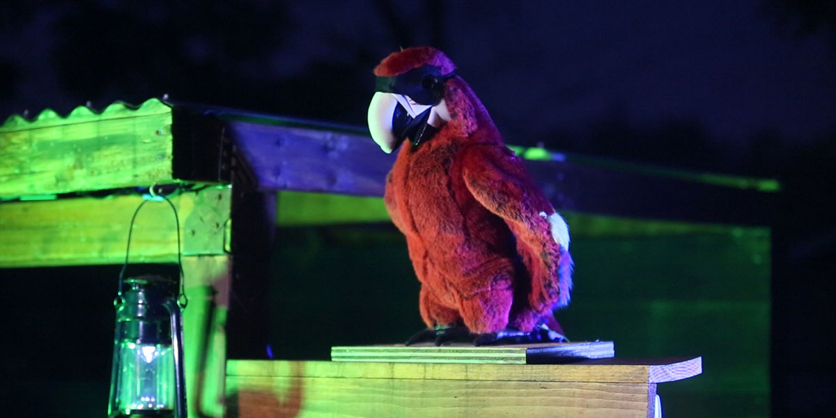
FIGURE 1. Bandit, the swashbuckling parrot.
I’d like to introduce you to Bandit, my Pirate Parrot. He was inspired by the birds in the Tiki House at Disneyland. Of course, any pirate worth his salt is going to have a parrot close by. Bandit will be an appropriate place to start our project of discovery as it’s a character I built from the ground up. He was constructed without the use of any premade components or mechanisms. The necessary materials could all be purchased from the local home repair store, and basic hand tools were all that were required to build the basic mechanism.
The servos and linkages came from ServoCity which carries a wide variety of servos, motors, controllers, and linkages. We will explore some of the many products they stock that will make our jobs easier in future builds, but for this project, I wanted to show what’s possible to do on your own.
One of the major obstacles I face when building a character is planning for the exterior dressing that will bring my mechanisms to life. The parrot was no different. We explored all sorts of options including toy parrots, yard decorations, and even feathering our own. After a year of searching, we finally came across the solution on a trip to the MGM hotel in Las Vegas, NV. While browsing in their store on the casino floor, we found the perfect item. A puppet — complete with a large area normally used to put your hand. This would now become the perfect vessel for the mechanical skeleton. With that problem solved, it was now time to design the inner workings, keeping in mind that whatever we designed had to fit inside the cavity of the puppet.
Everyone has a different philosophy when it comes to laying out the initial design of a mechanism. For me, I like to do a simple drawing to keep me from forgetting something and then construct a basic prototype. Rarely does the final project end up looking like the original design. It seems — more often than not — that the designs that work in my head don’t work quite as well once assembled. Adjustments and refinements are always necessary!
Bandit Begins to Take Shape
Before I even started the build, I needed to determine the specific movements that I wanted the parrot to do. In addition to speaking, I wanted the body to move in multiple ways: I wanted his jaw to move in sync with the audio track; have him be able to nod his head; bend at the waist; and have his wings move. For the range of motion, I prefer more subtle movements for my animatronics versus having their movements be wild and exaggerated. Just because a mechanism is able to have a wide range of motion doesn’t mean you have to use it. With these facts in hand, I could begin gathering the required materials and start laying things out.
For this project, I chose to utilize four HiTec 425BB servos which (along with the linkage parts) came from ServoCity. One servo was to move the jaw in sync with the audio track; one was needed to move the wings; and the other two to rock the body and neck forward and backwards. This model is my servo of choice as it has sufficient torque for most of my needs, it’s reliable, and the price is very reasonable. I don’t have any qualms about using a more powerful unit if it’s required, but I also don’t like to spend the money on more servo than an application requires (Figure 2).
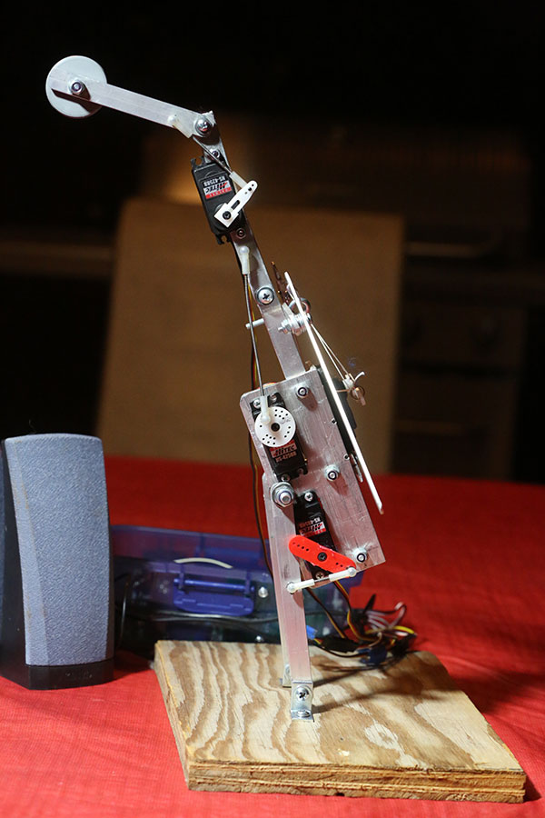
FIGURE 2. The completed skeleton ready to be dressed.
For the framework, I decided to go with aluminum stock that can be picked up from your local “big box” hardware store. It is convenient to be able to just run down the street to pick up material whenever I need it, but the cost can be high. I’m fortunate enough to have a large metal supply house which is where I pick up the majority of my steel and aluminum stock that I use to build my frameworks. I chose aluminum for this build as it had enough strength to get the job done while keeping the weight to a minimum. Aluminum is easy to work with using common hand tools.
A hack saw, a drill with appropriate bits, and a file are really all you need to get started building articulated mechanisms with aluminum.
We Have the Tools to Build Him
In order to have a place to mount the servos, I first had to cut and assemble the aluminum structure.
All three of the body servos would be attached to a single piece of 2 x 1-1/2 inch L shaped channel. This allowed me enough room to place the servos on both sides so they would not interfere with each other. The waist and neck servos were placed on the two inch side, and the wing servo on the 1-1/2 inch side.
I first traced out the dimensions of the servos. Then, using my Dremel tool with a cutting disc, I did most of the work and finished the cuts with a small hacksaw. The rest of the skeleton was constructed of 1/2” aluminum stock. I used the heavier 1/8” thick for the main body and 1/16” for the wings.
The body movement which allowed the parrot to move at the waist would be accomplished by adding a servo in the main body area and attaching a linkage to one of the legs. The parrot also needs to be able to nod his head. This was a fairly easy placement to figure out and install (Figure 3). The connection — like all those requiring a rigid link — was made using threaded 4/40” rod and ball joints.
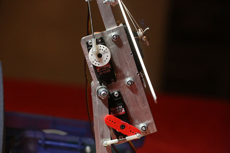
FIGURE 3. Neck and waist servo mounting.
Since the wings would move together, I could get the movement I wanted using a single servo. I installed the two wings on individual pivot points and added a center ring to run the lines. I then connected them to the servo horn using braided fishing line. This was an easy and inexpensive solution, and allowed me to easily adjust the range of movement of each wing (Figure 4).
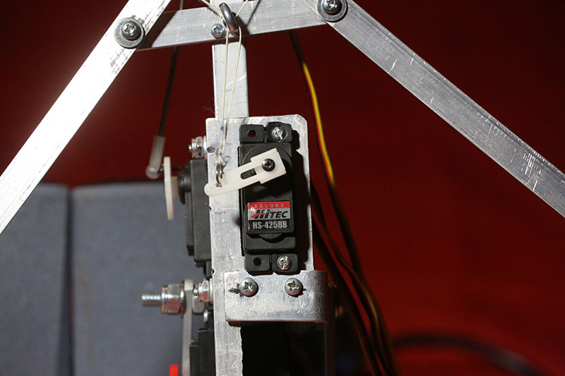
FIGURE 4. Wing servo and pivots rigged with fishing line.
The plan for the jaw servo was for it to be mounted in the chin and would again be connected using the braided fishing line. Getting this part of the mechanism to work properly ended up being the most time-consuming. I originally designed it using fishing line like I had done with the wings. This would open the mouth and rely on gravity to close it. This method worked fine with the wings where I had the added weight and leverage to allow this to function properly. However, the beak lacked sufficient weight to allow it to close quickly enough. My revised method was to use a rigid linkage that would drive the jaw open and then close it.
I would have preferred that the servo had driven the jaw linkage from the bottom instead of the top as it would have given me a better angle. However, the design of the puppet would not allow it to move freely that way. Just another one of the compromises you must often make in constructing something like this (Figure 5).
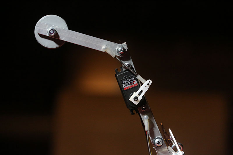
FIGURE 5. Final jaw servo mechanism.
The puppet did require a bit of careful surgery to allow the aluminum pieces to slide into the wings, as well as cutting slots for the leg pieces to go through the bottom of the feet. This made for a very clean installation with no signs of the aluminum skeleton visible. Once this was done, the legs were attached to the wooden base using two 3/4” corner brackets (Figure 6).
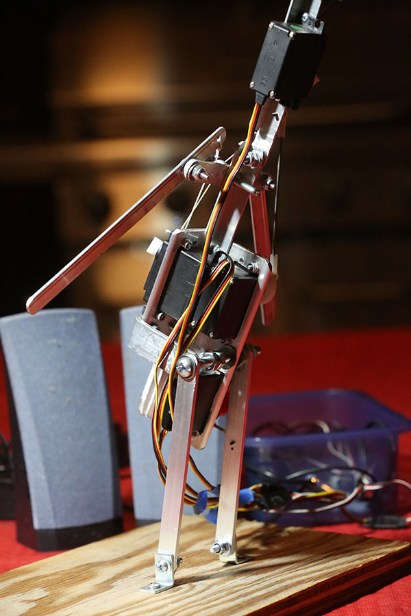
FIGURE 6. A view of the underside attachment points.
Bandit still needed a little something to finish him off. The addition of a mask really gave him a swagger and some extra character!
All the final attachments were made with bolts, washers, and lock nuts. I prefer to use the ones with the nylon inserts for a secure connection. While making the modifications, however, I usually use regular nuts to speed up assembling and disassembling. This makes things much easier, plus I don’t have to use a wrench to do it.
Bandit would entertain our guests from his own wood perch mounted to the side of our pirate facade (Figure 6). His base was constructed with ample room to hide his controllers and the necessary speakers from view (Figure 7).
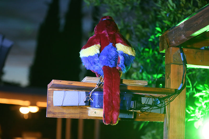
FIGURE 7. Bandit on his perch and all his hidden electronics.
Projects like this always require an extensive amount of tweaking. Finding the perfect placement for the servos and proper lengths of the linkages takes some patience. You need to be willing to adapt your original design in order to achieve the best result possible. Sometimes it is a matter of space, or it could be that a linkage is binding, or maybe you’re just not getting the exact movement you’re after. Whatever the reason, make sure to set plenty of time aside to make the necessary modifications. Some extra time spent on this step can make all the difference in the performance of your completed prop.
Bandit Needs a Brain!
I decided to use two of my custom boards to control the prop (Figure 8).
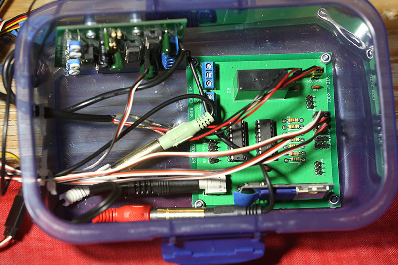
FIGURE 8. Controller boards secured in their home.
The first was my Kitchen Sink controller which provided me with the stereo audio player, and was able to control the three servos for the body movements. It uses a PICAXE 14M2 processor with an onboard Tenda stereo audio card (see Resources). This audio card utilizes an SD card to store the tracks and allows me to control the track being played, as well as letting me control the volume. Using this controller also allowed me to program it so that it either could be triggered by a passive infrared sensor (see Resources) or run on a loop.
To control the jaw and allow it to be synced to the audio, I used my version of the Scary Terry board. This board was originally designed by Scary Terry whose website you can find listed with the other resources. There have been several people who have revised the original design and this is my version.
An enclosure for the controllers was required, so I went to my favorite. When I first started putting together my own boards, I searched for a reasonably priced container to house them. I often found that I was spending more on the enclosure than I was on the completed controller. What I needed was something that was lightweight, easy to modify, watertight, and inexpensive. The best solution I found was in my own kitchen. The new plastic food containers used to store our leftovers were ideal for my needs. My wife soon tired of searching for missing containers and now routinely restocks my supply. It doesn’t even come out of my build budget anymore. Perfect!
The audio is first prepared using the free software download called Audacity. The original stereo track is split into a right and left channel, and the right channel’s audio is replaced with a tone track which drives the jaw circuit (Figure 9).
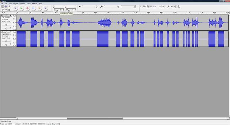
FIGURE 9. Audacity screenshot showing the split audio track.
If I was to build this now, I’d replace these two boards with one of my Frankenstein boards. This board allows me to combine all the functions necessary to control the parrot in a single board, thus making a cleaner installation as well as saving space. A link to my website showing the boards I’ve made to run my haunt is included with the Resources. Another modification I plan to do is to replace the existing jaw servo with one with a little more torque to improve the action.
The code I used was very basic. It took a little bit of adjusting to get it just right, but before long Bandit was moving. One of the reasons I like working with the PICAXE (besides its easy-to-learn programming language) is that the program editor is free (see Resources) Be sure to check out the code back in Listing 1.
With that, Bandit was ready to be put on display. You can check him out performing on his perch at https://youtu.be/OqnFj31UC80. SV
The success of this adventure into animatronics will rely on the participation of our entire collection of readers and builders. In order for this community to flourish, we all need to be willing to share and brainstorm our ideas. I welcome your contributions, your ideas, and resources. Your design may spark an idea or be the one puzzle piece someone is missing to bring their creation to life. Please submit ideas of things you'd like to see. Although the build list for the next several articles is already laid out, I'm always looking for new ideas for future articles.
LISTING 1
#Picaxe 18M2
'C.1 is to Tenda
'B.1 is Waist Bend
'B.2 is Spread Wings
'B.3 is Head Nod
Symbol Waist = B.1
Symbol Wings = B.2
Symbol Head = B.3
Symbol Tenda = C.1
Init:
serout Tenda,4800,
($EF);
'STOP MP3 module
pause 1000
serout Tenda,4800,
($E1);
'Set MP3 volume
pause 1000
Servo Waist, 50
Servo Head, 210
Servo Wings, 170
Routine:
servopos Head, 130
pause 1000
servopos head, 210
pause 1000
servopos Wings, 90
pause 250
servopos Wings, 170
pause 1500
servopos Waist, 150
pause 1000
servopos Waist, 100
pause 3000
serout Tenda,4800,($01)
'Start playing first mp3
pause 500
servopos Waist, 50
pause 1000
servopos Waist, 100
pause 3000
servopos Wings, 90
pause 250
servopos Wings, 170
pause 1500
servopos Waist, 150
pause 1000
servopos Waist, 75
pause 1500
servopos Head, 100
pause 1000
servopos head, 160
pause 1000
servopos wings, 90
pause 500
servopos wings, 170
pause 1500
servopos Waist, 120
pause 1000
servopos Waist, 90
pause 2750
servopos Head, 210
pause 1000
servopos head, 140
pause 1000
servopos wings, 90
pause 250
servopos wings, 170
pause 5000
servopos Waist, 150
pause 1000
servopos Waist, 90
pause 2000
servopos Head, 210
pause 1000
servopos head, 140
pause 1000
servopos wings, 100
pause 500
servopos wings, 170
pause 2500
servopos Head, 130
pause 1000
servopos head, 180
pause 1000
servopos Wings, 90
pause 250
servopos Wings, 170
pause 1500
servopos Waist, 150
pause 1000
servopos Waist, 100
pause 3000
for time = 1 to 60
'60 is the number of
'seconds of retrigger
'delay
pause 1000
'Pause for 1 sec
'next time
goto Routine
RESOURCES
ServoCity
www.servocity.com
Tenda Stereo Audio Board
www.mdfly.com/products/sd-card-mp3-player-module-rs232-ttl.html
Parallax Passive Infrared Sensor
www.parallax.com/product/555-28027
Scary Terry's Website
www.scary-terry.com/audioservo/audioservo.htm
PICAXE Program Editor
www.picaxe.com/Software/PICAXE/PICAXE-Editor-6
My Website
www.halstaff.com
YouTube Video
https://youtu.be/OqnFj31UC80
Article Comments