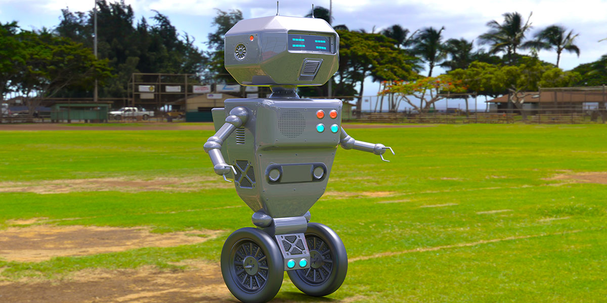
Sensing Orientation
By John Blankenship View In Digital Edition
If you are thinking of building a robot that needs a sense of balance, you will need an accelerometer and/or gyroscope in addition to the compass often used by hobby robots. This article will help you understand how such sensors work and will give you the background needed to make better purchasing decisions.
In the not too distant past, the ability to determine the spatial orientation of an object was far beyond the budget of most hobbyists. Today, there are many reasonably priced sensors available to help you build a walking robot or even a Segway-like balancing bot. An innovative hobbyist might even utilize an orientation sensor to help position the gripper on a robot arm.
Choosing a sensor that meets your needs, though, can be confusing. There are magnetometers (compasses), accelerometers, and gyroscopes, as well as various combinations of these devices often referred to as IMUs (inertial measurement devices). Understanding exactly what each device measures and how they work can be helpful in determining what you need for your projects.
Magnetometer
The sensing elements in a magnetometer are typically composed of various thin metallic surfaces integrated with semiconductor layers in a manner that produces voltages proportional to an intersecting magnetic field. The readings from two sensors mounted at right angles to each other can be used to calculate a compass heading.
Accelerometer
The sensing elements in an accelerometer measure forces from gravity or acceleration. Basically, each sensor is a capacitor where the distance between the two plates is proportional to the forces acting on those plates. The change in capacitance is converted to a change in frequency or voltage with appropriate circuitry integrated internal to the accelerometer chip.
Gyroscopes
Unlike accelerometers, gyroscopes are not affected by static forces such as gravity. Gyros respond to changes in angular rotation. Their sensing elements are tiny vibrating mechanisms that produce forces perpendicular to the vibration and proportional to the angular velocity. As with accelerometers, these forces alter the distance between the plates of tiny integrated capacitors.
IMUs
Since magnetometers, accelerometers, and gyroscopes all respond to different forces, it makes sense to combine two or even all three of these sensors to create an inertial measurement device (IMU). The data from multiple devices makes it possible to accurately depict the sensor’s orientation. A simple example can clarify this idea.
Figure 1 shows two magnetometer elements (labeled X and Y) mounted at right angles to each other. Assume the compass is mounted on the robot so that element Y is aligned with the robot’s heading. Notice in this figure that the robot is currently facing north. In this case, element Y will detect the maximum magnetic effect since it is aligned with the field. Element X, on the other hand, will detect no magnetic field since it is perpendicular to it.
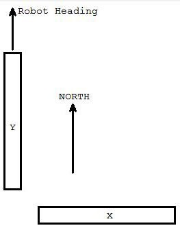
FIGURE 1.
Figure 2 shows the same robot (and sensing elements) now facing NW by 65°. Each of the two elements will now detect only a percentage of the maximum magnetic field. The actual amount each element detects will be proportional to the SINE or COSINE of the angle between the north heading and the element’s heading.
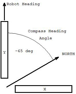
FIGURE 2.
Once the forces on elements X and Y are measured (call them Fy and Fx), the compass’ (and thus the robot’s) heading can be calculated using ATAN2(Fy,Fx) — a function available in most computer languages. Note: ATAN2 is preferred over the ATAN functions because ATAN2 works with angles in all four quadrants.
The above calculation requires that the sensing elements be level — that is, the compass should be parallel with the Earth’s magnetic field. If the compass is tilted, then the reading from each of the sensing elements must be adjusted because the relative tilt angles will reduce the field detected by the elements. This simple example explains why it can be important to have multiple sensors. Acceleration data, for example, can detect tilt that can be used to modify the magnetometer data to ensure accurate readings even when the compass is not level.
In a similar manner, the compass information can be used to augment the data from other sensors to provide accurate information about the orientation of the entire sensor group.
When combining the readings from multiple sensors, the mathematics can quickly become complex and involve both trigonometry and matrix operations. The complexity becomes even worse when you realize that all the data must be mathematically smoothed (filtered) to get more usable information. Fortunately, there are IMUs that have an integrated processor that performs the math operations for you. Such devices are far easier to use, but (as you would expect) the convenience comes at a much higher cost. In general, more expensive units will give you more reliable data at faster data rates.
What Do You Really Need?
Many projects do not require a full IMU. If, for example, your mobile robot is always operating on a level floor, you should be able to get usable compass headings from a simple magnetometer. If your robot operates over rough terrain, though, you will need a tilt-compensated compass (or purchase a compass and accelerometer and learn to write your own compensation code).
If you are building a Segway-like robot that does not make sudden starts and stops, then a simple accelerometer might provide all the tilt information you need for balancing. Keep in mind, however, that sudden movements can invalidate the tilt information for short periods of time.
Acquiring Data
All of the above problems are important, but there is even more that must be considered. Most orientation sensors are interfaced using an I2C bus which can be complicated — especially for beginners. Many microcontrollers have I2C libraries that help with the interfacing, so check before you begin reinventing the wheel. The HMC5883 compass shown in Figure 3 is available from many sources (including Parallax) in a variety of footprints. Its simplicity is a good place to start if you want to experiment with an I2C device.
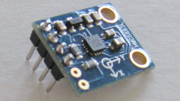
FIGURE 3.
More recently, additional interfaces for inertial sensors have emerged. For example, the ADXL335 accelerometer shown in Figure 4 provides analog outputs that are proportional to the unit’s tilt. This makes interfacing extremely easy for processors with integrated A/D inputs such as the Arduino. The resolution is often slightly reduced when analog interfacing is used, but that should not be a problem for most hobby applications.
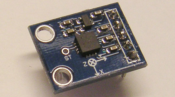
FIGURE 4.
Some sensors offer both an I2C and a TTL serial interface making them easier to interface with almost any microcontroller. Having both serial and I2C ports is often true of IMUs that contain an integrated processor such as the nine degrees-of-freedom Razor from SparkFun, shown in Figure 5. It comes in two models, one of which also has a USB interface.
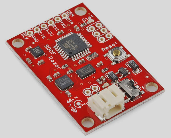
FIGURE 5.
If you want a complete interface solution, consider the CyberAtom IMU that is still available from ExpTech. This particular model provides a USB interface as shown in Figure 6.
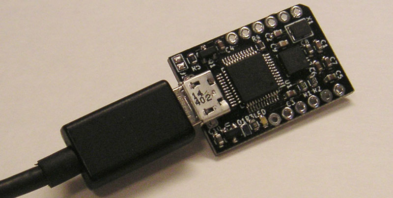
FIGURE 6.
I found it to be easier to use than any IMU I experimented with. CyberAtom even provides studio software that shows a graphical version of the sensor that mimics the movements of the real one; refer to Figure 7.
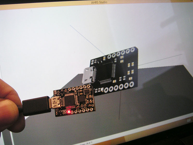
FIGURE 7.
A major advantage of the CyberAtom is that it comes with tutorials for both the Arduino and Raspberry Pi, APIs for both C and Python programmers, and dedicated SDKs for Windows and Linux. The CyberAtom’s speed and stability were beyond my expectations, but many projects probably don’t need the power of a high-end/more expensive unit.
Inexpensive Options
As mentioned earlier, many hobby robots can get by with a non-compensated compass or a stand-alone accelerometer. If your project requires an IMU, though, there are many low cost units based on the MPU9255 which replaced the MPU9150. Remember, however, low cost versions will generally not have integrated processors which will require you to write the code to fuse the data from multiple sensors into usable information.
I worked with an MPU9150 based unit from EZ-robot as shown in Figure 8; chosen because of closeout pricing I couldn’t resist. It provided all the raw sensory data, but trying to convert the data to usable information was challenging to say the least. Similar units without integrated processors (both 9150 and 9255) are available from many sources.
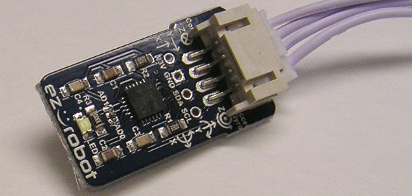
FIGURE 8.
Conclusion
As you can see, there are many options if you are building a robot that needs information about its orientation. I have several projects planned, so perhaps you will see some of these sensors in a future article. SV
Article Comments