The Multi-Rotor Hobbyist — Adding Telemetry to the ELEV-8
By John Leeman View In Digital Edition
Pilots of regular aircraft have a panel of instruments that indicate important parameters such as the aircraft altitude, air speed, attitude, and engine system status. As multi-rotor pilots, we are often operating by look and feel. We can estimate our altitude through experience and the aircraft attitude through the use of colored propellers or motor struts. In this episode, we are going to add a telemetry kit to the ELEV-8 v3 to get real time aircraft data sent back to our tablet in the field.
Introduction
In the October 2016 issue of SERVO, we built the Parallax ELEV-8 v3 kit and began to explore its capabilities. The ELEV-8 has since made appearances as an instrument platform for a meteorology package and has other projects planned. One of the first things I wanted to add was the capability to send vehicle data back to the ground.
Before we go any farther, I must stress that as the pilot, your first priority is safe operation of the aircraft, but having your spotter glancing at a screen full of vehicle data could be very valuable if you lose your orientation or would like an altitude check. Recording the telemetry data could be useful when performing a post-crash analysis, or trying to measure and improve the vehicle performance.
This month, I’ll walk you through the process of adding the ELEV-8 900 MHz Telemetry Kit (Figure 1) (https://www.parallax.com/product/32480) and go through the troubleshooting that occurred when things didn’t work on the first (or second) try. While this article is specifically about using the kit and software from Parallax, the telemetry system is based on XBee radio modules, so there’s something to learn here no matter what kind of multi-rotor or radio system you choose to use.
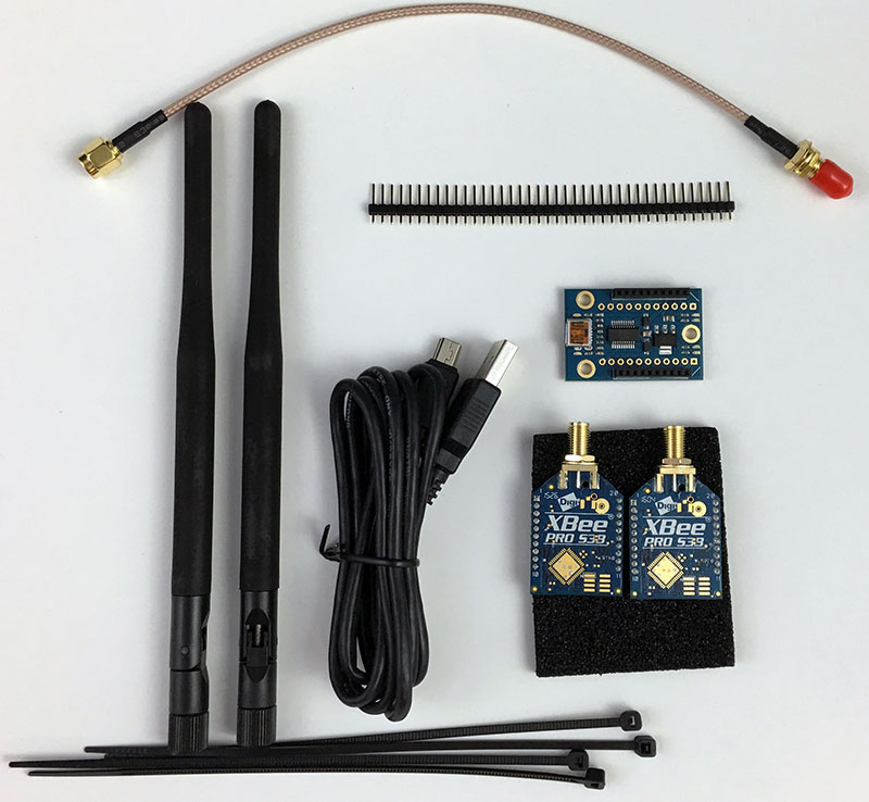
Figure 1: The complete telemetry kit from Parallax includes two XBee radios, antenna, USB adapter, USB cable, zip ties, header, and RPSMA extension cable.
XBee Introduction
XBee is a series of modules from Digi that lets you easily make connected devices in everything from a complex mesh network to a simple “wireless serial port” type configuration. They use the IEEE 802.15.4 networking protocol, and are a really nice and inexpensive way to add a wireless component to many projects. If you want to learn more about using wireless protocols and peripherals in your project, check out the book, Building Wireless Sensor Networks by Robert Faludi (http://amzn.to/2eJ6FMl). The radios used here are the 900 MHz models. This is important as the radio system we are using to control the quad is a 2.4 GHz system. Using multiple 2.4 GHz systems on the same quad would likely result is lots of interference and possibly losing control of the vehicle.
I have had no previous experience with the XBee products other than reading articles about projects that had used them in Nuts & Volts and SERVO. This was a good chance to dive in and learn a little bit about how they work. I’m thinking that they could be an even simpler solution than Wi-Fi for sending data from sensor packages down to the ground, but they are slightly more expensive. The kit that we’ll install retails for $149. The Pro 900HP modules that we’re using sell for $39 individually.
XBee Configuration
We need to set up the parameters the XBee radios will use to communicate. Digi provides a configuration utility called XCTU on their website (https://www.digi.com/products/xbee-rf-solutions/xctu-software/xctu). Download and install this tool. It is available for Windows, Mac, and Linux systems. Digi has even produced a short introduction to XCTU video that is helpful to watch (https://youtu.be/X_fHDvV_q98). Using XCTU, you can easily upgrade the firmware of XBee radios, check the signal strength and RF environment, and configure settings of all devices on an XBee network.
By now, you probably have the FTDI Virtual COM Port (VCP) drivers installed on your system, but if you don’t, go ahead and do so. The drivers are available on the FTDI website for most operating systems (www.ftdichip.com/Drivers/VCP.htm). You’ll need this to communicate with the flight controller and the ground side radio.
While you’re dealing with software, go ahead and make sure your flight controller and ground station are up to date. Just after the publication of the ELEV-8 v3 review article, the flight controller and ground station received updates with the release of version 2.0 of the software. This software offers some great stability improvements and is worth taking the five minutes to upgrade.
If you need some help uploading the new firmware to the flight controller, be sure to check out the instructions in the October 2016 article. The most recent versions of all of the software can always be downloaded from the Parallax GitHub repository (https://github.com/parallaxinc/Flight-Controller). Just click on the “Releases” tab and download the most recent set of files. You must be running the same version of the flight controller firmware and ground station software for things to work.
It is worth keeping an eye on the repository as there are always changes being made to the software (the ActiveDevelopment branch containing the most bleeding-edge versions). There is also an “Issues” section where you can see what bugs are currently reported and what new features are coming down the pipeline. The Parallax forums (https://forums.parallax.com) are also a good place to visit. Most of the ELEV-8 discussions there occur in the Robotics section of the forum. First, we need to set up the correct baud rate on each of the two XBee radios. To do this, we’ll put each radio in the XBee USB adapter board, connect an antenna, and connect it to the computer (Figure 2). Never power up an XBee without an antenna attached! Powering the radios without an appropriate antenna connected can cause permanent damage to the radio.
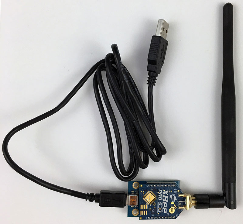
Figure 2: Clip one of the radios into the USB adapter, add an antenna, and it is ready to plug into the computer for configuration. Remember that you should never power up an XBee with the antenna removed.
So, connect an antenna (included in the kit) to the RPSMA connector and plug in the adapter board with a mini USB cable. Open up the XCTU application. Once inside, click on the “Discover Devices” icon that looks like an XBee module outline with an hour glass (Figure 3). A window will come up asking you to select which COM port to look on — select the port associated with your USB adapter board (Figure 4). If you’re unsure, disconnect the board, click “Refresh Ports,” then reconnect and click “Refresh Ports” again. The port that disappeared and then reappeared is the one you want.
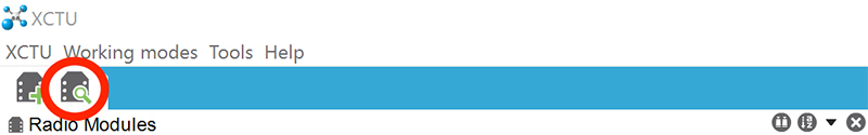
Figure 3: The “Discover Devices” button is in the upper left-hand side of the XCTU window (circled in red).
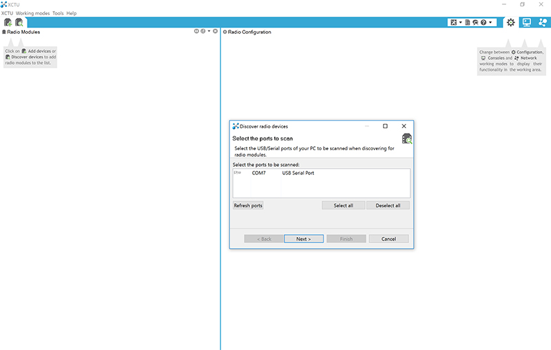
Figure 4: Select the appropriate COM port for your USB adapter. In my case, it was the only device plugged into my Microsoft Surface at the time.
Once done, click “Next” and set the parameters to use when connecting. With new modules, the defaults will be fine. If you have already configured the modules or are reusing modules, adding more baud rates to the list could be useful. I generally added 57600 and 115200 baud for future use (Figure 5). Once done, click finish and XCTU will scan for any attached radios.
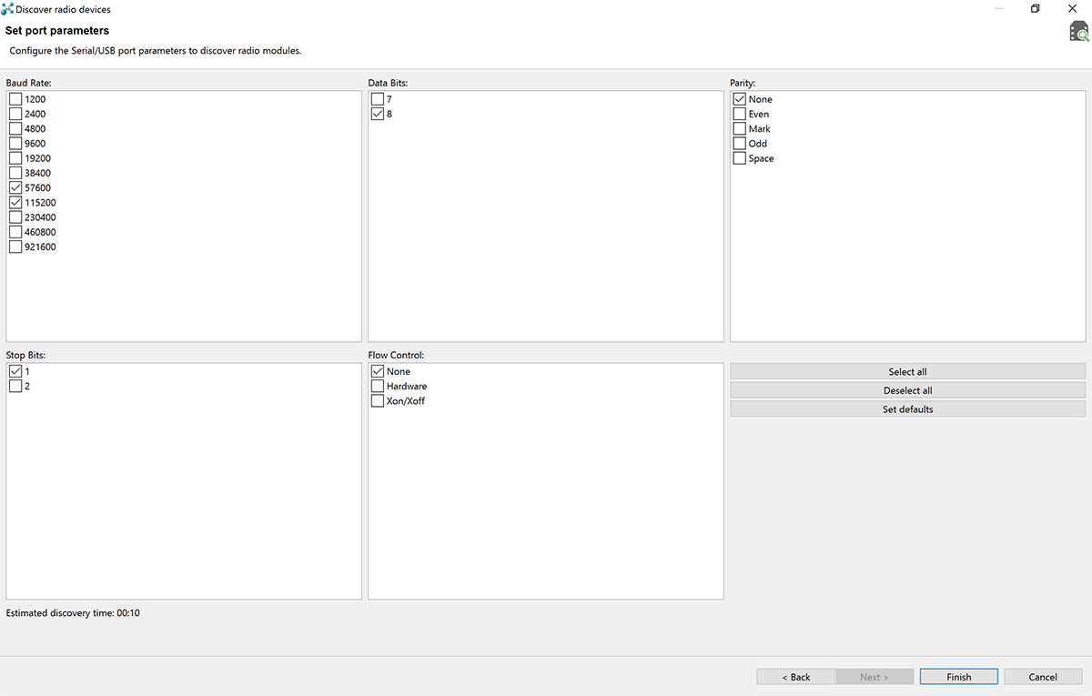
Figure 5: Select the search parameters used to discover devices. I add 57600 and 115200 since those are common settings used and ones that we will use later.
After the scan completes, the module will show up in the left-hand pane of the application. Click the module and wait for the software to load up and display the settings for the radio (Figure 6). In the settings, we need to change the “BD Baud Rate” field to 57600 (Figure 7). (Be sure to read completely through this article before doing this yourself, as there are several modifications that we’ll make to this procedure.)
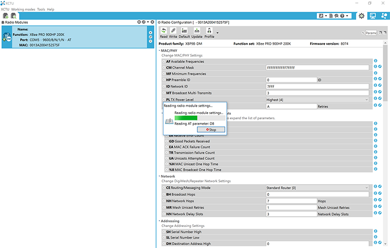
Figure 6: Once the radio is discovered, click on it and wait for all of the settings to be read out and displayed.
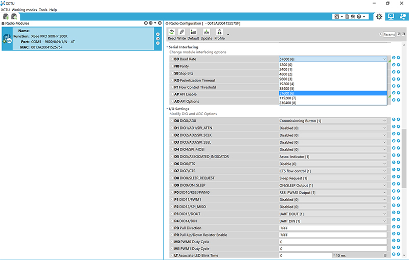
Figure 7: Set the radio baud rate (BD setting) to 57600 baud.
Once you have changed the radio’s settings, click the pencil icon to write the settings to the radio (Figure 8). Unplug the USB cable and swap out the radios, then make the appropriate changes to the second radio as well. I find it helpful to label the radios “G”round and “A”ir to keep things straight when working with them. Doing the ground side radio second also means one fewer swap of the modules!
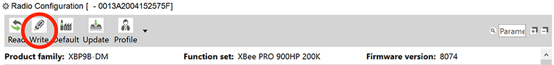
Figure 8: Write the new settings to the radio by clicking on the pencil icon in the upper left of the radio configuration pane.
Hardware Installation
Installing the hardware on the ELEV-8 takes just a few minutes. Remove the smoked acrylic cover from above the flight controller PCB (printed circuit board). (Don’t forget to keep track of the screws! I find keeping a couple of old espresso cups on the bench is perfect for this task.) Remove the panel nut and lock washer from the RPSMA antenna connector since they are not needed for this application. Carefully align the radio with the plug-in headers on the flight controller and insert the module (Figure 9). The direction is marked on the board and the location of the antenna connector makes it relatively obvious as well.
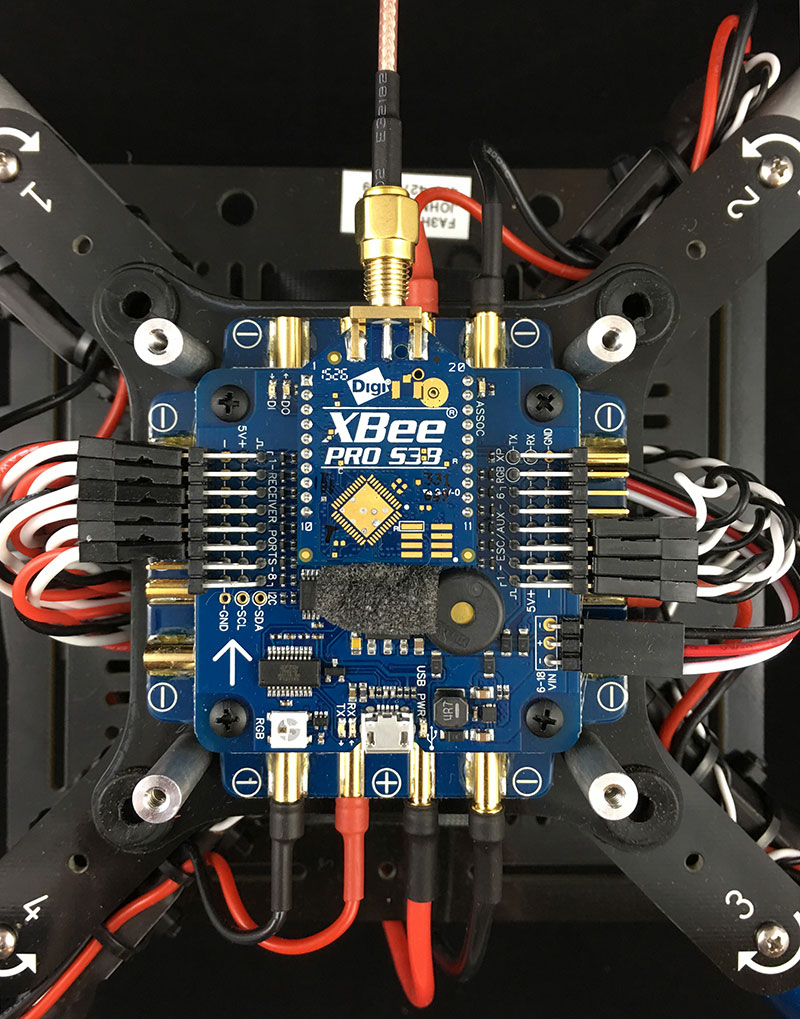
Figure 9: Install the air side XBee by inserting it into the headers on the flight controller PCB. Don’t forget the piece of foam below it to provide an air baffle for the barometric pressure sensor.
I sandwiched a foam block that helps baffle the air around the pressure sensor under the edge of the module to help hold it and to be sure it is indeed covering the sensor. I would hold off on replacing the top cover for now until everything is working, but don’t forget it at the end of the process! The antenna provided is of the “rubber ducky” type, but is relatively rigid. You can attach it directly to the radio’s RPSMA connector, but I would advise against it. When you crash, any force on the antenna will be directed to the RPSMA connector and will very likely break the XBee PCB. If the crash is bad enough, I could even imagine the flight controller PCB becoming damaged.
Parallax includes a small extension cable with the telemetry kit that provides one possible solution to this problem. You simply connect the cable to the radio and route it through the frame of the quad to the edge of the base plate by leg number four. You can then connect the antenna to the cable and use zip ties to secure the antenna to the landing gear (Figure 10). I think this solution looks much cleaner and is more crash-proof. On the Parallax website, they show using a short piece of heat shrink to make the ground side radio/USB adapter setup more permanent and eliminate any shorting hazard from use on metal surfaces. While this is a good idea, I would again hold off until everything is working. If you intend to keep up with development of the software/hardware, it could also be inconvenient as the radios may periodically need to be reconfigured. A small project box is a nice solution or a 3D printed bracket.
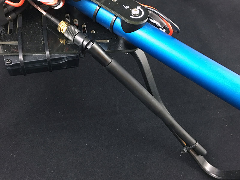
Figure 10: Route the RPSMA extension cable through the frame and install the antenna. Mount the antenna to the landing gear with zip ties. This is much more resilient in a crash than having the antenna installed directly onto the XBee’s antenna connector.
I designed a 3D printed bracket with a monitor clip that attaches the radio to your laptop/tablet screen. You can download the STL files at the article link. My main goals were to keep the solder pads accessible, make it easy to pack in a way that it won’t break apart in my field bag, and to keep it simple!
A “T” shaped bracket with recessed areas for 4-40 nuts seemed like a good solution. I printed one out, press-fit the nuts, and installed the XBee USB adapter with some 4-40 machine screws. The clip for the bracket is easily installed for use and removed for storage (Figure 11). I thought that this added a nice professional touch (Figure 12) and still allows for easy changing of the radios for development. It’s also one less thing for your spotter to hold or prop up in the field.
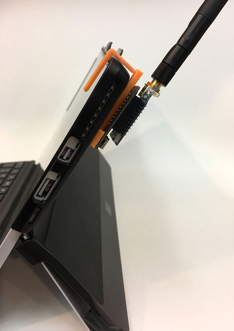
Figure 11: The clip is a loose fit so that it can be easily removed for transport and storage without breaking any parts. I haven’t had any problems with it slipping out when in use.
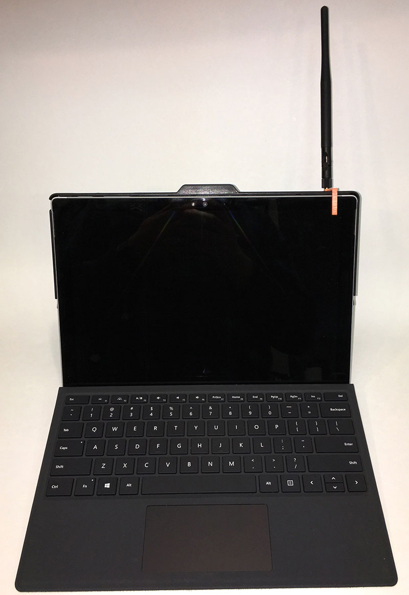
Figure 12: The clip is designed to fit on pretty much any screen, even with a thick case. It sits nicely on my Surface that I use as a field computer.
Troubleshooting
In theory, if you plug in the ground side radio, open up the ground station software, then power up the ELEV-8; the radios should connect and data should start flowing almost instantly. Unfortunately, this didn’t happen for me. I spent the better part of an afternoon going over all of the steps, verifying that the radios had saved the settings, and didn’t get any leads. It was time to breakout the test equipment and see what was happening.
The first rule of troubleshooting is “Thou shall check voltages,” so I did. Everything looked fine. Next, I dug out my TI (Texas Instruments) SA430 spectrum analyzer. I picked this up several years ago on special for about $50 and have used it multiple times when troubleshooting RF links. I saw some peaks during packet transmission (Figure 13), so I immediately jumped to this being a software issue and began a discussion on the Parallax forum.
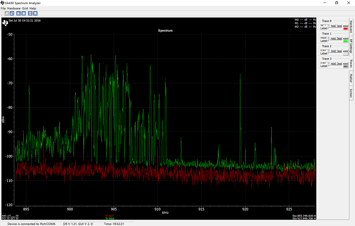
Figure 13: At least one of my XBee modules was putting out power during the handshake data transaction, but I couldn’t tell if the handshake was actually taking place.
With the help of several people at Parallax and forum moderator, Publison, we determined that there was a bug with the numbering of the COM ports in the Windows ground station software. Changing the COM port number to 5 or higher should solve it. So, I connected the radio, went into the “Devices and Printers” settings of Windows, and found the device.
In the hardware tab under “USB Serial Port” and Properties, there is a button labeled “Change Settings.” After clicking that, a properties window came up; in the Port Settings tab under Advanced, you can change the port number. (Windows is seemingly famous for these convoluted settings windows — what a pain!) I set my radio to COM10 and fired everything back up ... Nothing. Still no communication at all.
I tried sending the “BEAT” command to the setup using a terminal program to ask the quad to send its data. I even wrote a Python script to do this multiple times, but did not receive a response from the quad. We finally decided that it may actually be a hardware problem. So, Publison sent me his working XBee radio set to try. By doing some component swapping, we determined that one of my radios in the kit was faulty and sending virtually no signal on transmit.
Parallax quickly sent a replacement and I was getting connection between the quad and the ground station in no time. Whew! I thought I was home free, but Publison and I quickly realized that the telemetry was locking up very frequently and may or may not resume after 15-30 seconds. Parallax was just about to release version 2.0 of the flight controller software and the ground station, so we waited for the release. After upgrading, the problem persisted.
After some work, the folks at Parallax and forum members were able to reproduce the problem. It looked like some of the XBee settings needed further modification. The most crucial was changing the “CE Routing/Messaging” setting on the ground side radio to be a “Non-Routing Module” (Figure 14). After saving the settings to the XBee, I once again fired things up and it worked! I was able to maintain a solid connection to the ELEV-8 with no dropouts or other problems.
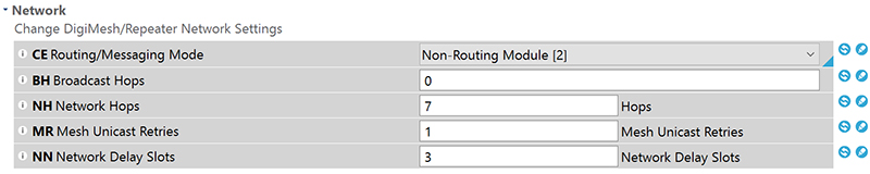
Figure 14: Change the ground side radio’s routing/messaging mode to be a “Non-Routing Module.”
Developer Jason found out that the latency of the system could be greatly reduced by setting the radios up in a point-to-point mode instead of broadcast mode. To do this, you note the DH/DL and SH/SL ID of each radio and set them equal to each other (Figure 15). This makes the XBees only talk to each other and removes some of the overhead associated with each data transmission. He also recommended setting the RR (retry count) on the base station to “A” (10), but setting the flight controller to a lower value, like 3 (Figure 16). This means that we’ll get more current data at the expense of sometimes dropping an older packet — a perfectly reasonable tradeoff. It was also found that the serial data rate of the XBee radios can be set to 115200 baud (this must be done on both radios). If you choose to do this modification, you’ll need to change the line of code in the firmware that sets the serial communication rate of the Propeller microcontroller with the XBee (Figure 17).
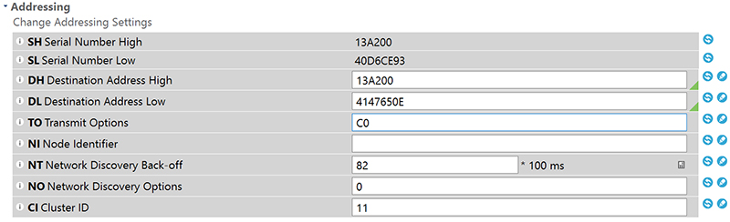
Figure 15: Set the destination address high and low fields to the serial number high and low fields of the other radio in the pair. This reduces the communication overhead and makes the latency of the telemetry much lower.
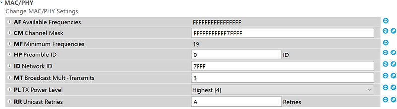
Figure 16: Change the retry count from “A” to “3” on the flight controller radio. The ground radio can be left at “A.”
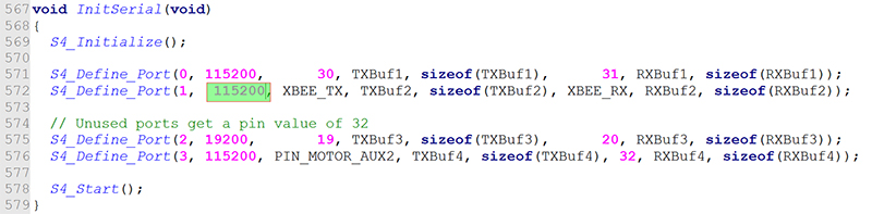
Figure 17: Change the XBee baud rate in the flight controller firmware if you decide to use 115200 baud communication. The field to change is highlighted.
This troubleshooting effort really shows how great forums and open source collaboration (and really the GitHub issue tracking) can let companies iterate and problem-solve very quickly. After the changes, things are running pretty smoothly.
Viewing Telemetry
Once you have the XBee radios talking, you can easily view a lot of information in the ground station software. You can even perform tasks like calibrations without the need to connect to the flight controller with a USB cable!
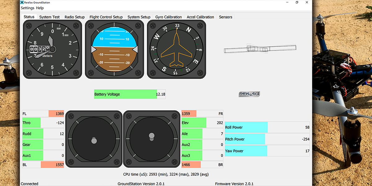
The “Status” tab of the application shows you the commanded and actual orientation of the quad, power to each axis of rotation, inputs from the radio, battery voltage, and the standard altimeter, virtual horizon, and heading instruments (Figure 18). This is the one your spotter will likely be looking at. Holding your quad and tilting it around helps you get a sense of how the instruments work and how much latency there is.
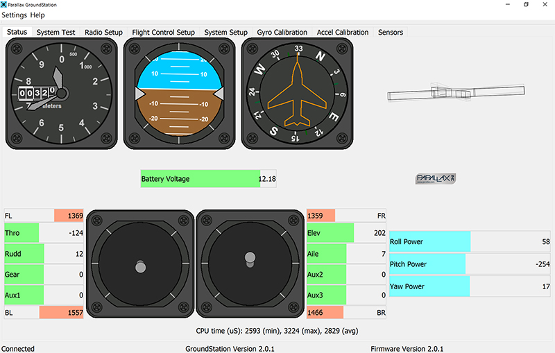
Figure 18: The status tab of the ground station software has all of the essentials in an easy-to-follow layout. Your spotter can read it with a quick glance.
The other tab that’s interesting to look at for telemetry is the “Sensors” tab. Here, you can view a time-series graph of whichever sensors are selected on the left side of the window. Scrolling the mouse wheel zooms in time and you can drag the plot around. Viewing everything on one plot is generally too much, but looking at all components of the gyro, magnetometer, or accelerometer (Figure 19) is very useful. An attitude plot can be nice as well (Figure 20).
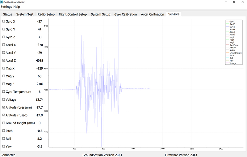
Figure 19: A plot of the three-axis accelerometer Z component during a very short demonstration flight. Notice the takeoff acceleration and slow decent.
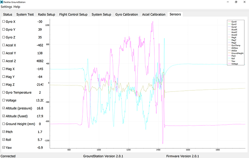
Figure 20: The attitude of the quad shows me rolling (cyan) and pitching (purple), but leaving the yaw (yellow) relatively constant.
If you’re anything like me, you want to collect data about everything. The more data, the better. There was a request on the GitHub page for a way to log the received telemetry data to a file for later analysis. It was implemented in the ActiveDevelopment branch to be available with the next major release. I thought this would be a good opportunity to learn how to build the software from the development branch so we could play with new features. I must stress that this means working with “under development” software that could very well have bugs and cause issues for you. So, experiment at your own risk. Most readers of this magazine aren’t afraid of bleeding-edge software though!
I managed to build the ground station from source, but decided that’s a bit beyond where most people would be comfortable working. There has been some discussion on GitHub about ways to improve the telemetry logging, and I hope that it will be in the next release of the software. When that happens, we’ll probably come back to the topic and look at ways to plot the large amounts of telemetry data from different flight controllers.
Tools that many people are familiar with (like Microsoft Excel) won’t handle the large files generated, but there are a plethora of other tools available — many for free!
Closing Thoughts
Now you have data flowing from the air to the ground! Your spotter can call out your true heading, altitude, and other information to you in real time. I’m anxious to get my hands on the flight logs because I can think of several really interesting uses for them, including wind speed estimation, improved battery endurance calculations, and black box style investigations of crashes, just to name a few.
In the meantime, remember to keep your eyes on the quad, talk with your spotter, and collect lots of great data! SV
Article Comments