Do Androids Dream of Being Connected to the Internet?
By Evan Woolley, Bryce Woolley View In Digital Edition
If 1980’s sci-fi is to be believed, connecting robots to the Internet should be undertaken with extreme caution. That said, controlling robots over the Internet seems like a logical extension of the much ballyhooed Internet of Things (also known as the IoT). The Internet of Things refers to the fairly nascent phenomenon of connecting “things” (other than computers) to the Internet. These things usually have some sort of sensor-based tangible interaction with the world — like the “smart” thermostat from Nest which lets you control your home temperature from your smartphone.
More things are joining the IoT as of late, with their membership in this futuristic club most often denoted by the prefix “smart” — like a smart fridge that can sense its own contents, which we suppose would be helpful for folks unable to make their own grocery lists and yet somehow still be able to set up a smart fridge.
Much of the Internet of Things is populated by relatively passive devices that are most often used for monitoring — whether it be monitoring the energy usage in your home or on a larger scale (the smart grid), or monitoring the location and fuel levels of your various trucks (for fleet management) if you’re some kind of industrial mogul.
So, what if you want to control something a lot more sophisticated than a thermostat over the Internet, like a robot? Setting a temperature dial from your smartphone is one thing, but a robot should be a lot more maneuverable. Is there an easy way to induct your robot into the IoT? Would a smartphone make a serviceable controller? Is this how Skynet got started? Sometimes all a rover wants to do is phone home, so we were going to roll the dice, hope our own personal bot-net didn’t become self-aware, and connect a robot to the Internet.
Honey, I Shrunk the Internet Gateway
We really started thinking about over-the-Internet control for a bot used in an Actobotics Agent 390 project we did a few years back. With the Agent 390 base and some Jaguar speed controllers in hand, we needed to sort out a control system for wreaking havoc with our mini tank. Our regular radio controller had been used with our un-retired combat robot, Troublemaker (who made a triumphant return to competition at one of the last RoboGames). So, we used the Canipede robot control module and 2CAN Ethernet gateway, and created a wireless network for the bot with an onboard travel router.
We were able to control the bot using the uCANDrive app on our smartphones, so it almost sounds like we’ve already achieved what we’ve set out to do this time. The bot may have had a Wi-Fi connection, but it wasn’t like what we envisioned for something connected to the Internet. We had to follow the bot to keep in range of the network, and the dodgy travel router did not provide a reliable signal. Our vision of high tech Wi-Fi control conjures up images of driving as slick and self-assured as Johnny 5 escaping from NOVA in “Short Circuit,” and not driving as jerky and unreliable as Johnny 5 after he’s accosted by those hooligans in “Short Circuit 2.”
So, we researched our options for connecting a robot to the Internet and turning our smartphones into robot controllers. We wanted something that could work with our phones because smartphones seem like they could be the ideal controller for a robot — they’re ubiquitous, and there would be no need for tracking down a radio for your bot. Would a smartphone touchscreen provide the sensitivity needed for robot control? Or, is the IoT destined to exclude robotic companions?
It only took a quick search to find exactly the technology we were looking for: the ESP8266.
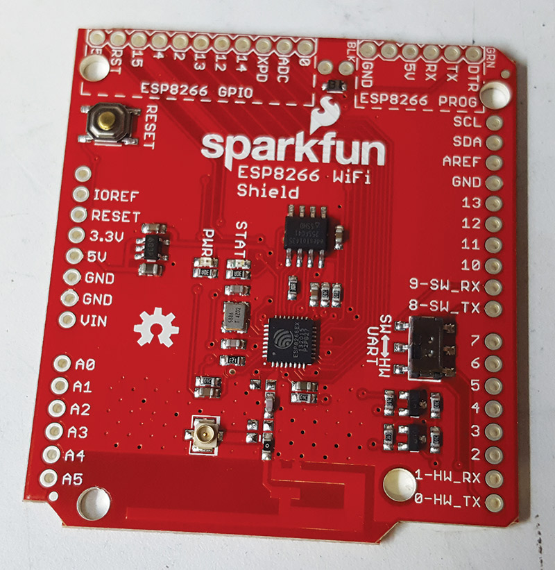
The SparkFun ESP8266 Wi-Fi shield.
The ESP8266 is a Wi-Fi chip with an integrated TCP/IP protocol stack that can give any microcontroller access to a Wi-Fi network. That’s pretty rad. The ESP8266 was introduced by the Chinese manufacturer, Espressif just a few years ago, and the chip really took off with Western tinkerers with the introduction of the ESP-01 module from third party manufacturer, AI-Thinker in 2014. The most striking things about these ESP modules are their size and affordability. They are about the size of a movie ticket stub (albeit a long rectangular one), and they can cost under $4. What a time to be alive! (For more on the ESP8266, see "Meet the ESP8266" from Nuts & Volts)
As with the Arduino and Raspberry Pi, a dedicated user base has coalesced around the ESP8266. One of the great features of such a vibrant user base is the development of numerous accessories and hardware improvements on the fairly minimalist ESP module. We found one such improvement from one of our favorite sources of electronic awesomeness: SparkFun. SparkFun’s ESP8266 Wi-Fi shield combines the Wi-Fi connectivity of the ESP8266 chip with the shape and familiar pin breakouts of the Arduino. The Wi-Fi shield can even be used as a stand-alone board, and users can load their own custom code onto it using an FTDI breakout.
We, however, found that option a little risky. Your custom code overwrites the AT-command firmware that comes on the unit, and the custom code might not work with the AT commands essential for connecting to Wi-Fi. So, we planned to use the Wi-Fi shield as, well, a shield.
The Arduino Strikes Back
The Wi-Fi shield works on the 802.11 b/g/n standard and the familiar R3 Arduino pin layout. The Wi-Fi shield would be a perfect fit for our Arduino Uno, but before connecting to the Internet there was some assembly required. The SparkFun page on the Wi-Fi shield recommends using the stackable headers, and that’s exactly what we did.
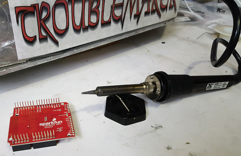
Soldering up the Wi-Fi shield.
Soldering on the stackable headers is quick work that we completed in Robot Central one afternoon with Troublemaker (hibernating again after RoboGames, but hopefully not for 13 years this time) watching over the proceedings. We find it to be quite a relaxing experience actually — inserting the stackable headers in the board means that it can stand steady as you dot your iron along the underside of the board, not unlike MacReady dipping the hot wire into various blood samples in an attempt to identify “The Thing.” The soldering is so straightforward that it would make an excellent introduction to the skill for newcomers to the electronic craft.
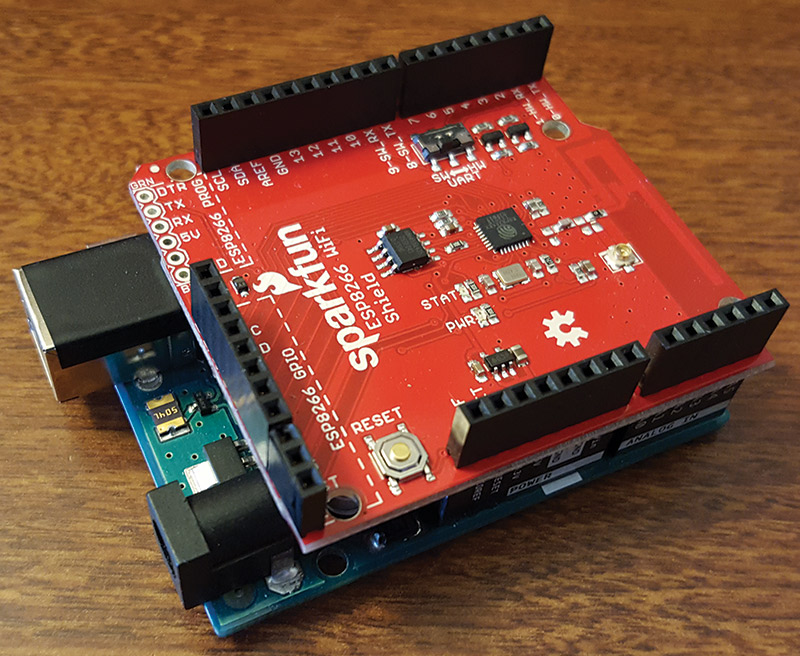
Stacking the Wi-Fi shield on an Arduino Uno.
The SparkFun website contains a very useful online Hookup Guide for the Wi-Fi shield, which is not as risqué as it sounds. The Hookup Guide walks through the entire process of setting up and using the shield, and even links to a tutorial on soldering for the newcomers.
The Hookup Guide also gives a nice overview of the shield hardware, with bright high-res close-ups of the board and its pinouts. One of the interesting parts of the board hardware is the serial switch which allows you to choose whether the RX and TX signals go to the Arduino’s hardware ports (pins 0 and 1) or serial port (pins 8 and 9).
The Guide recommends leaving the switch in its default position of selecting the software serial. If you switch to the hardware serial, all the programming will also go to the ESP2866, which the Guide cryptically cautions could send the ESP2866 into an unknown (though recoverable) state.
Just like shrinking hapless kids with a shrink ray, just because you can recover their normal state doesn’t mean the initial digression is a good idea. So, we resolved to stick with the software serial. Sticking with the software serial also meant that we could stick with the default baud rate of 9600.
Other hardware features include a reset button (which resets the underlying Arduino but not the Wi-Fi shield) and a helpful LED status light that blinks when trying to connect and stays solid with a successful connection.
Upon becoming oriented to the hardware, we were ready to stack the shield onto our Uno. Our Uno has a USB-B connector for programming which is a little on the bulky side. To avoid any electrical impropriety (the USB connector sat just below the solder pads for the FTDI breakout), we covered the top of the USB connector with electrical tape. In any event, the proximity of the USB connector to the pads (even if they were occupied by some 90 degree male headers, as suggested) should not be a problem because the Hookup Guide strenuously makes the point that good clearance between the Wi-Fi shield and the Uno is necessary to avoid possible interference with the Wi-Fi antenna by the Arduino’s ISP headers. So, we backed the Wi-Fi shield off of the Uno a bit, aiming for a fit that was delicate but firm, like the swaddling you would do on E.T. to prepare him for an airborne ride in a bike basket.
The Wi-Fi has its own library of Arduino awesomeness, with all the header files and examples you could ever want. There’s a link to the library directly in the Hookup Guide. The first example the Guide covers is a simple demo of some of the basic functions of the AT library. It connects to a Wi-Fi network, finds its local IP address, tries to connect to a remote server (example.com) to get a webpage, and finally sets up a server of its own. The well-commented code provides a good explanation of the various functions, and to get the example working you only have to change two lines at the top of the code. All you have to do is enter in the SSID and password for your Wi-Fi network in the appropriate spot. Easy as pie, but once we loaded up and ran the program, we felt a little like Matthew Broderick in “WarGames.” We were in.
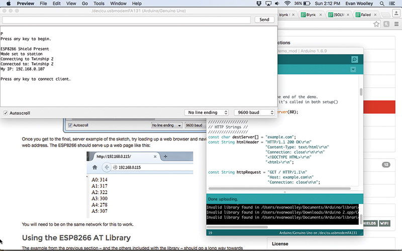
Internet connection successful!
The progress of the program is best followed in the serial monitor. It will alert you if you’ve connected to the Wi-Fi network (or failed to do so), and it will require several keystrokes to run through the functions like connecting to the remote server and whatnot. Everything worked exactly as it was supposed to. Our trusty Arduino Uno was connected to the Internet — but could we officially claim it to be inducted to the IoT?
In the Blynk of an Eye
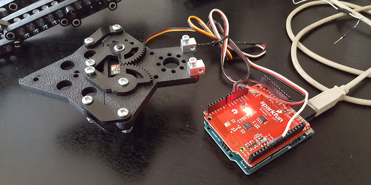
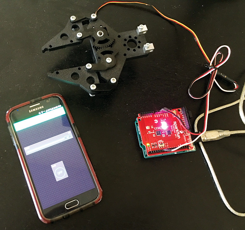
Not quite yet, we reckoned. Having the serial monitor tell us that the Uno was connected to the Internet was one thing, but we wanted proof that was a bit more tangible — we wanted to move a thing. A perfect candidate for that thing was one of our Actobotics grippers. The Arduino had plenty of power to open and close the servo powered appendage, and it seemed appropriately tangible in that it would literally allow us to reach out and touch something over the Internet. Wiring the claw to the Wi-Fi shield was easy enough — we used individual wires to pick up the disparately placed power, ground, and PWM pins. But how would we control it?
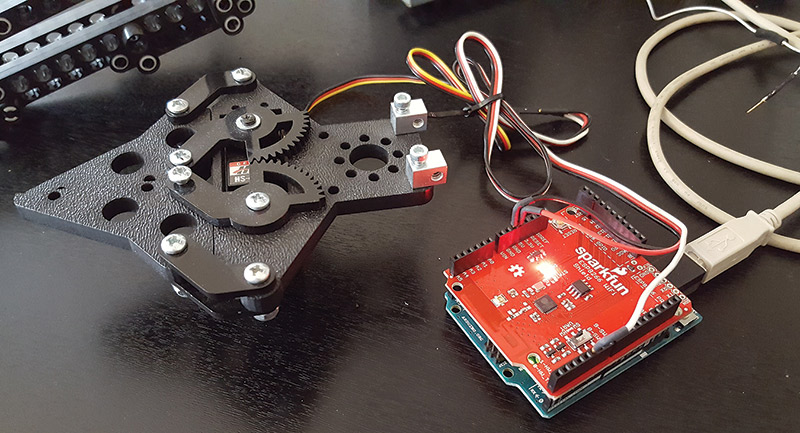
Testing the Wi-Fi shield with an Actobotics gripper.
The answer was Blynk. Blynk is a smartphone app that allows users to create control interfaces to connect with things like the ESP8266, and the various Arduino, SparkFun, and Raspberry Pi implementations of that Wi-Fi gateway. Blynk positions itself as a great way to induct stuff into the IoT, and the eye-catching free app certainly got our attention.
When you start a new project with Blynk, you are given a very important piece of information: the authorization token. The authorization token ensures that whatever hardware you’re programming is only accessible by your smartphone. The app conveniently allows you to email the rather long authorization token to yourself for some handy copying and pasting a little later on. Other than that, all you need to do to set up a project is give it a name and select your hardware. We selected the Arduino Uno.
The Blynk interface itself evokes The Grid from “Tron,” with its dark background and neon lines. Creating control interfaces with Blynk is as easy as dragging and dropping widgets onto your screen because that is literally what you do. The widgets can take many forms: buttons, sliders, and even a two-axis joystick. You can place display widgets too — everything from simple value displays to gauges.
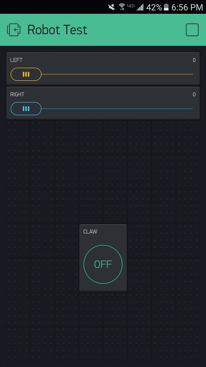
Making a control interface with Blynk.
Once you place a widget, you can click on it to open it up. In the ensuing screen, you can name your widget (something as blandly descriptive as “Servo 1” or as colorful as “Deathclaw;” whatever floats your decimal point), select which pin the device is on, and set a few other parameters that might include the range of your slider (which we set to 180 to account for the limited range of the servo). You can even change the color of the widget.
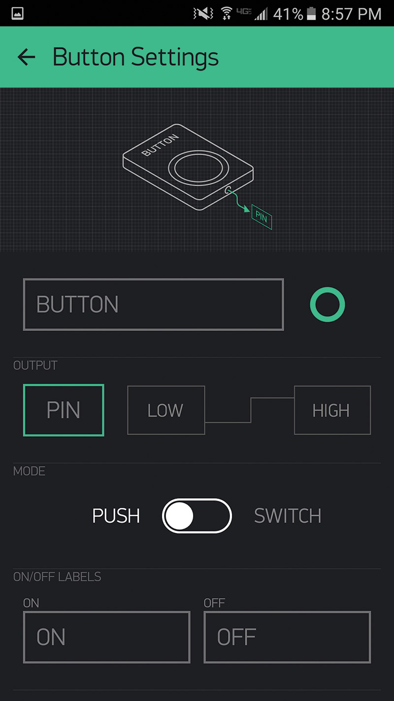
Editing widgets in Blynk.
To start with baby steps, we crafted the simplest controller possible: a humble button. Now, we had to program the Uno. Blynk comes with its own host of Arduino libraries which are freely downloadable from GitHub (linked to from the Blynk website). To make downloading as painless as possible, everything is included in one folder, but that means importation into Arduino needs to be done manually.
Internet of Claws.
Fortunately, both the SparkFun and Blynk websites have step-by-step tutorials on how to do just that. All it entails is navigating to the correct folder on your computer (the Arduino “libraries” folder) and copying the various Blynk folders into it. You’ll need to restart the Arduino IDE (integrated development environment) after feeding it new libraries, but once you do there will be a plethora of Blynk sketches under the Examples tab.
The sketch we were interested in was a demo under the Boards and Shields category specifically for use with the SparkFun Wi-Fi shield. The example code is well commented and surprisingly short. The code requires only a few modifications. Just like with the first demo we used, we had to enter in our Wi-Fi SSID and password. You also need to fill in the Blynk authorization token, and this is where copying and pasting out of your email comes in handy. There’s only one more step, but it’s an important one.
The example code has lines for both the software serial setup and the hardware serial setup. By default, the software serial lines are commented out and the hardware ones are used. We swapped that, and the last detail was to ensure that the RX and TX pins were properly identified in the code. We checked the board, saw that pin 9 was denoted as RX and pin 8 for TX, and entered those numbers.
It struck us as way too easy. The program, however, compiled without incident. We uploaded the program and opened the serial monitor. The serial monitor declared that the board was unable to connect to the Wi-Fi.
That struck us as strange. We had no problem connecting to Wi-Fi with the previous demo program. Fortunately, the Blynk forum is a comprehensive resource for all things troubleshooting, and we were eventually able to discover the problem (though it had us feeling a little silly). The Wi-Fi shield was having trouble connecting to the Internet because we had pushed the shield farther down onto the Uno, and the interference with the Wi-Fi antenna was as effective at messing up our Internet connection as was someone using the phone when you were using a dial-up connection.
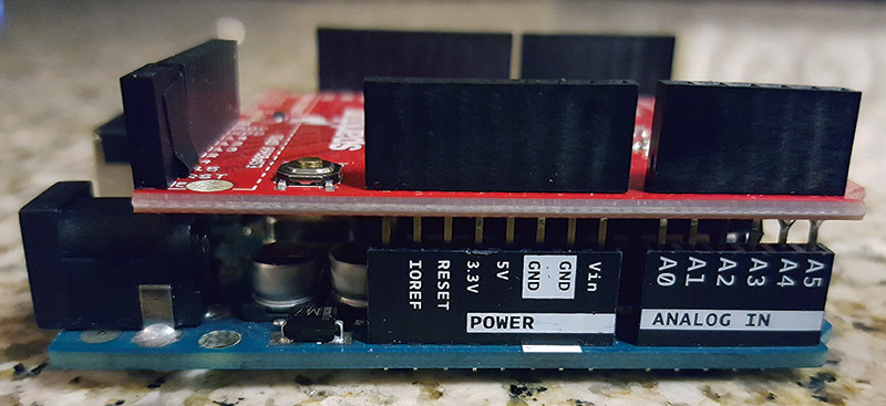
Too close for comfort.
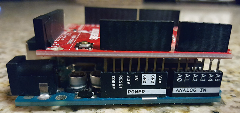
Extra room for the Wi-Fi antenna.
We gave the shield a little more breathing room, and the serial monitor no longer mentioned being unable to connect to the network, but gave a different problem instead. The serial monitor would give the cryptic message “Failed to disable echo.” After returning to the supremely helpful Blynk forums, we found the solution to this problem too. We had incorrectly designated the RX and TX pins in the program. Even though we went with the numbers as they were printed on the board, in the program those numbers actually have to be reversed. That’s not to say the RX and TX pins as labeled on the Wi-Fi shield are wrong — the issue boils down to a difference in definition — RX and TX with respect to which device? In any event, swapping the pin numbers put us in business.
We uploaded the fixed program and watched the serial monitor with anticipation like what Marty and Doc Brown must have felt as they exited the DeLorean to see whether they really were taken back to 1955. The line “Connecting to the network” hung on the screen for a few agonizing seconds before the monitor confirmed that we were, in fact, connected to the Internet. We started the Blynk app, tapped the onscreen button, and when the claw jerked to life we felt a feeling of triumph like what George McFly must have felt when he knocked out Biff Tannen.
Each tap of the button would only open the claw a little bit, so we went back to The Grid and made a new interface using a slider. The slider opened and closed the claw like a dream, and it showed impressive sensitivity.
And with that, we had inducted a robotic claw into the Internet of Things.
Rover Phone Home
A claw is cool, but we wondered how effective the Blynk app (normally intended for traditional IoT functions like activating a light or something like that) would be for controlling a robot. We rigged up a simple driving base using two servos to power the wheels, but the Uno (or Wi-Fi shield) couldn’t accommodate both because there was only one 5V pin. So, we busted out the SparkFun PWM shield which comes with a whopping 16 PWM channels.
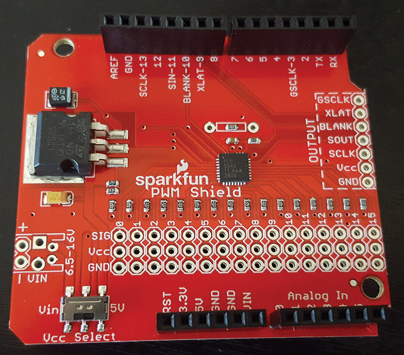
The SparkFun PWM shield.
We soldered on some stackable headers and some female headers for a few PWM channels. We wired up the servos, stacked the shields, and soon had a super simple rover eager to join the IoT. We set up a control panel with Blynk using two sliders, and turned it all on.
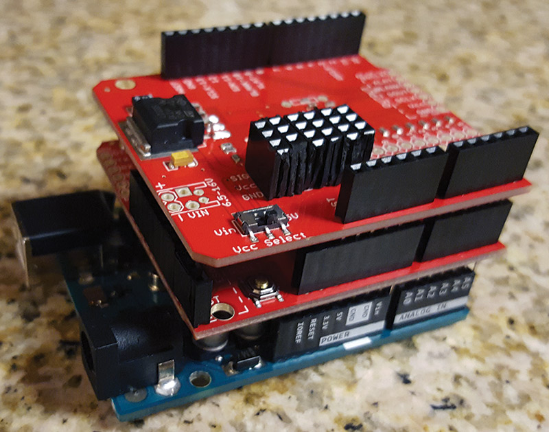
Stack attack.
It was not exactly to the point where we feared we would have to dispatch a blade runner to track down and retire it. The servos jerked a little bit, but were not really responsive to the controls. We think the problem is that the setup was a little too power hungry. We were running it off of the wall power as recommended to increase the stability of the wireless connection, but power requirements are a big consideration when stacking more than one Arduino shield. The Wi-Fi shield is one of the more power hungry shields to begin with. The PWM shield — sourcing 5V pins out the wazoo — is also a member of the power hungry club.
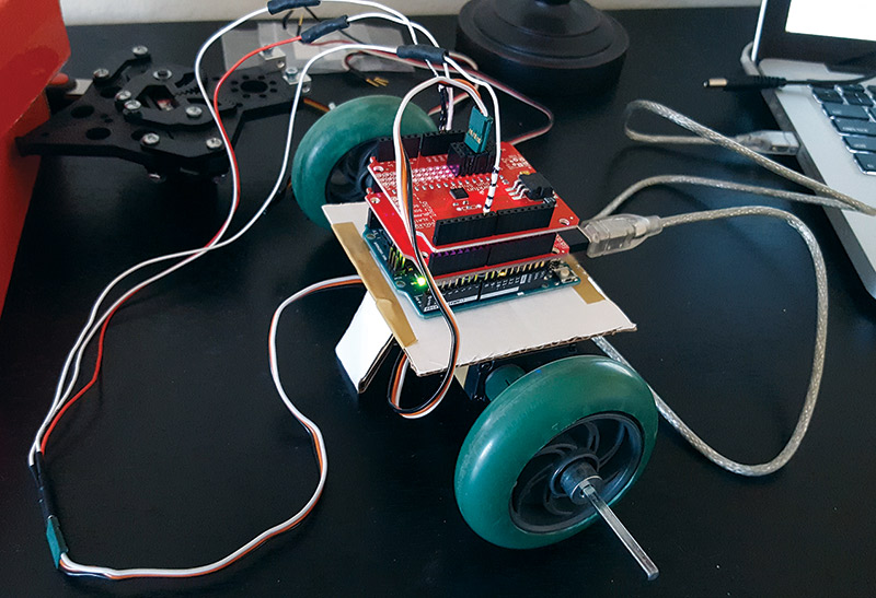
Internet of Robots.
However, that doesn’t take away from the awesomeness of the ease with which we connected the Actobotics gripper to the Internet. The SparkFun Wi-Fi shield and Blynk provide very promising (and affordable!) platforms for initiating robots into the IoT.
No matter what Terminator says, we’re excited to keep building and connecting bigger and better bots to the Internet. SV
Resources
Sparkfun
www.sparkfun.com/products/13287
Blynk
www.blynk.cc
Article Comments