Servo Magazine ( April 2017 )
New Sensor on the Block!
By Eric Ostendorff View In Digital Edition
Flashback to my February column, when I answered a question about ultrasonic range finders and I talked about sensor fusion: the popular term for sampling data from several different sensors. I mentioned IR proximity sensors and more specifically Sharp’s family of IR distance measuring sensors as a good complement to ultrasonic sensors. No sooner did I send that article off to the fine editors of SERVO Magazine that I found another type of sensor: a laser obstacle sensor for $10-$15. It was available on eBay, Amazon, and RobotShop, but there wasn’t much information about it.
I HAD to have some. Lasers are just plain cool. Around 1970, my older brother got a ruby laser rod for the princely sum of $75 from Edmund Scientific and made a death ray for his school science project. Focusing intense energy bursts from glass-melting flashbulbs, he managed to burn spots on his school sweater and a few other unsuspecting objects. It was downright dangerous and very demonstrable. These days, much tamer laser pointers and laser diodes can be found at dollar stores! Still a potential hazard to eyesight, though, so be careful in all you do.
You can still spend lots of money on laser sensors these days (Figure 1).
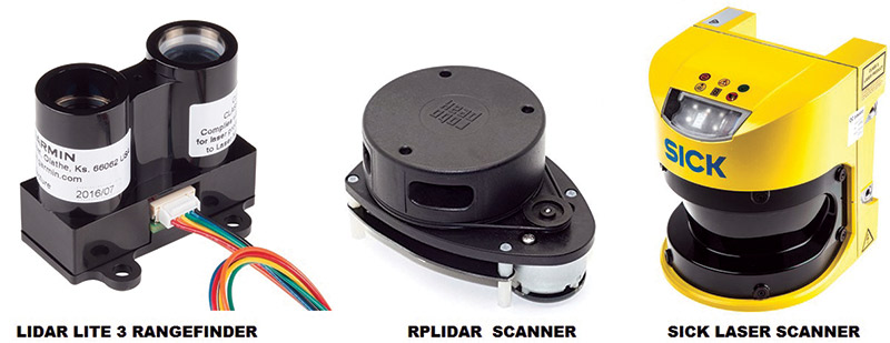
FIGURE 1.
A Lidar-Lite v3 laser range finder (left) sells for $150 at https://www.sparkfun.com/products/14032; $445 gets you DFRobot’s RPLIDAR rotating scanner (center) at https://www.amazon.com/Degree-Laser-Scanner-Development-RPLIDAR/dp/B00LGC2CTI. Or, if money’s no object, grab a few $5,000 SICK laser scanners (right) as used on many DARPA Grand Challenge AUVs at www.plccenter.com/en-US/Buy/SICK%20OPTIC%20ELECTRONIC/S30A6011.
A few years ago, I found a very cool LEGO site by Phillipe/Philo at www.philohome.com/sensors/lasersensor.htm showing how to retask a $4 copy machine paper sensor into a very cool digital laser sensor. The S6986 sensor IC (Figure 2) is getting rare and hard to find.
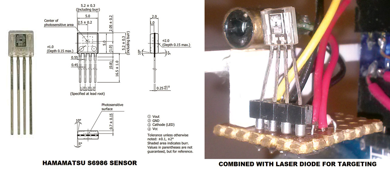
FIGURE 2.
Ultimately, I ordered a hundred direct from Hamamatsu after some fancy footwork and getting approved by their sales department. The stand-alone sensor costs several dollars and can be fashioned into a very useful sensor by adding a laser diode. The IC both modulates the laser beam and detects the reflection.
I have used it in several projects, using it to sense Scotchlite retroreflectors at over 10 feet away without any lenses. In fact, I won Jameco’s “Coasterbot 2” contest with a robot using this system (Figure 3) for navigation and targeting.
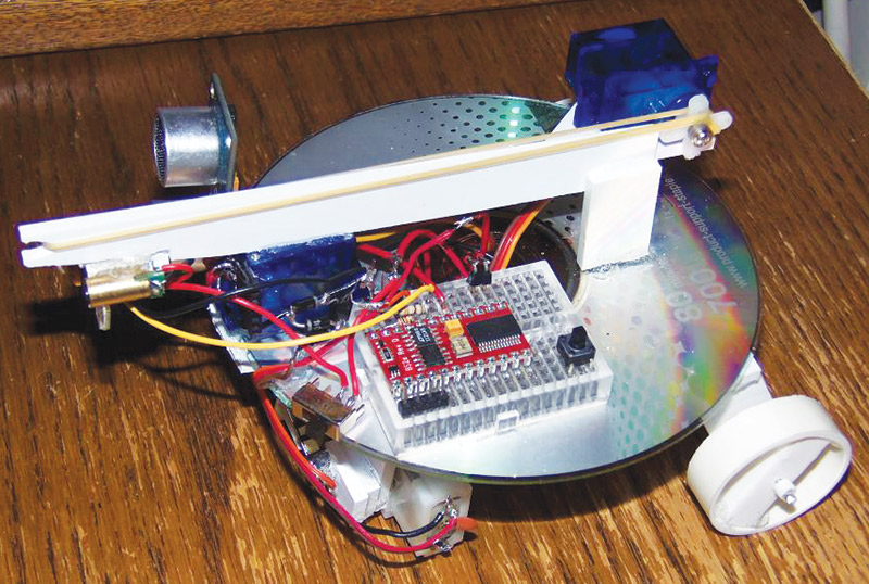
FIGURE 3.
Info is available at www.jameco.com/Jameco/workshop/challenge/challenge-coasterbot2results.html and my video entry is below. I actually contacted Philo to thank him, and he was happy to see his work inspired me several years later. So, again, it’s a neat sensor which can be hacked into a DIY laser sensor module with some effort.
In contrast, the new laser sensor shown in Figure 4 comes ready to use. Figure 5 shows the schematic.
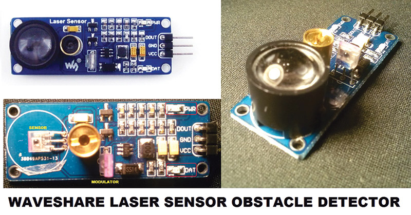
FIGURE 4.
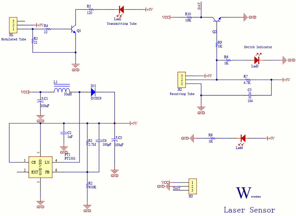
FIGURE 5.
You can find more information on Waveshare’s “Obstacle Detector” at www.waveshare.com/wiki/Laser_Sensor. It looked to me like an easily sourced drop-in replacement for the Hamamatsu sensor, even though it was only listed as an obstacle detector.
I ordered three $10 sensors from www.robotshop.com/en/obstacle-detection-laser-sensor.html and was pleasantly surprised.
The datasheet specs a wide supply voltage range from 2.5V-5.0V and, in fact, most of the onboard components are for the PT1301 voltage boost circuitry for the laser. Powered from 5V, the sensor draws 28 mA and the peak output voltage is 4.79V. Powered from 3.3V, I measured a 47 mA draw and peak output voltage of 3.17V, so this is a very user-friendly sensor.
The laser receiver is a clear three-pin package which looks like a phototransistor or the Hamamatsu sensor. Adjacent to the brass laser tube is a similar-looking component which is apparently the laser modulator. The datasheet lists the modulation frequency as 180 kHz. Seeking more information, I emailed Waveshare, which is a Chinese company. Their reply:
Hello, dear
Your question: The laser modulation is actually 180 kHz? And what does the extra phototransistor near the brass laser do?”
Our engineer said: That is the modulated tubes, which is modulated the laser as a regulated rate and send, there is a receiving tube under the lens, which is used for receiving the fixed rate
So, there you have it! Straight from the manufacturer!
You can see my initial test video below. The module has two red SMT LEDs: one for power on, and one indicating detection of a reflected modulated laser signal. The output signal is normally high/active low — much like a 38 kHz IR receiver module. The removable lens is held on with double-sided tape, and is critical to achieve sensing distances over ~8 inches.
Closer than that, the lens interferes with proper function due to beam alignment and parallax effects. Max range is very dependent on the color and reflectivity of the surface. Here are some results from my range tests:
- White surface max range ~36”
- Black plastic computer case ~12”-18”
- Black resin watch strap ~12”
- Dark brown fabric ~8”
- Black fabric not detected
- Sunny outdoors, Scotchlite reflector 60+ FEET
As an obstacle detector, this sensor has range issues with black or dark objects, so it would be wise to have a companion sensor; either ultrasonic or Sharp IR sensors, which are less color sensitive. Personally, I see more potential in using it as a long-range Scotchlite reflector sensor.
My outdoor tests to sense a Scotchlite retroreflective sticker in sunny conditions showed a working range of over 60 feet in my wiggly handheld tests. Probably more if the sensor and reflector are firmly fastened down. You could easily make a long distance break-beam sensor system, either a perimeter alarm, or (as my drone-racing buddy Jon suggested) a finish line timing sensor. There are many possible applications.
In the toy business, when a product has a quirk, we often say “if you can’t fix it, feature it.” This sensor’s color sensitivity may work against it as an obstacle detector, but in the right situation it brings something new to the party. My first order of business was to try it on a line following robot.
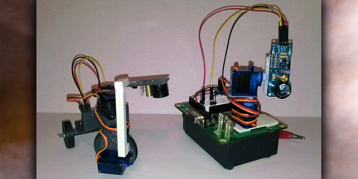
Using just one sensor seeing black or white, it would have to be an edge detector. I built the small tricycle robot shown in the opening shot and Figure 6.
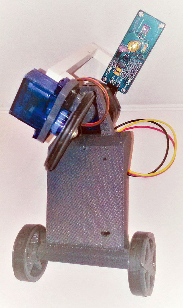
FIGURE 6.
The front drive wheel is steered via servo and the sensor is mounted overhead to steer along with the wheel. It is used without the lens and looks downward at the line about an inch ahead of the wheel. The tiny PICAXE program in Figure 7 follows the right edge of a wide black line quite simply by zigging left when white is seen and zagging right when black is seen.
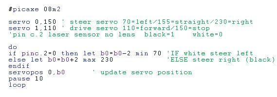
FIGURE 7.
My video demonstration shows the line follower steering system is in constant oscillation; somewhat like the old “galloping ghost” control system used in the earliest days of radio control: https://www.youtube.com/watch?v=IBxXsRwRn1M.
That wiggling is the price you pay for such a minimalist one-sensor edge following system. If we could add more sensors, it would help reduce oscillation. Unfortunately, these laser sensors interfere if they overlap each other’s field of view, so we’re stuck with using one sensor — unless you want to multiplex several sensors so only one laser is on at a time. I did that on an S6986 based laser tracker project you can see below.
Back to the single laser sensor, vehicle dynamics could be improved by adding a second servo and decoupling the sensor from the wheel. In this system, the extra servo would oscillate/scan the sensor across the line edge while the steering servo holds a more stable position.
There are much faster line following robots out there; my “waddling duck” (as someone named it in the PICAXE forum) robot certainly won’t win any speed contests. However, it’s the epitome of simplicity and the red laser dot is highly visible, showing where the robot is ‘looking’ at any time. People understand it at a glance without much explanation.
I’ve taught students in college and I know it’s easier to engage whole classes when projects are simple and seemingly obvious. When people say “even I could build that,” I’ve done my job.
In similar fashion, I wanted to make a simple optical scanner using this laser sensor. Its sensitivity to color makes it a low resolution digitizer of sorts. There’s no electronic sensitivity or contrast adjustment for what’s detected as black versus white; it triggers at a preset value of reflected laser signal.
That signal will vary based on the color and reflectivity of the object seen, as well as the distance to the object. I settled for scanning a simple B/W image of our namesake SERVO. I joined two HXT900 9g servos directly together with CA glue to make a quick and dirty pan/tilt mechanism to do a mechanical raster scan with the laser sensor.
There are some gorgeous little pan/tilt brackets for these servos on eBay for under $2 (Figure 8), but I decided to avoid their extra mass and momentum since I want to accelerate the servo quickly between scan lines.
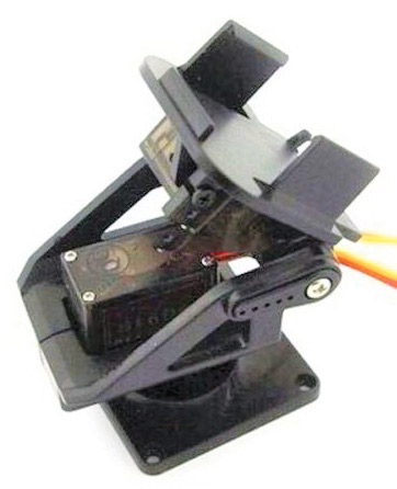
FIGURE 8.
Still, the mechanical scan rate is the system limiter — glacially slow by microcontroller standards — and almost any processor can easily keep up.
I grabbed an old favorite, my BASIC Stamp 2 Homework board (Figure 9) and foam taped it atop a heavy lead-acid battery with rubber feet for stability while scanning.
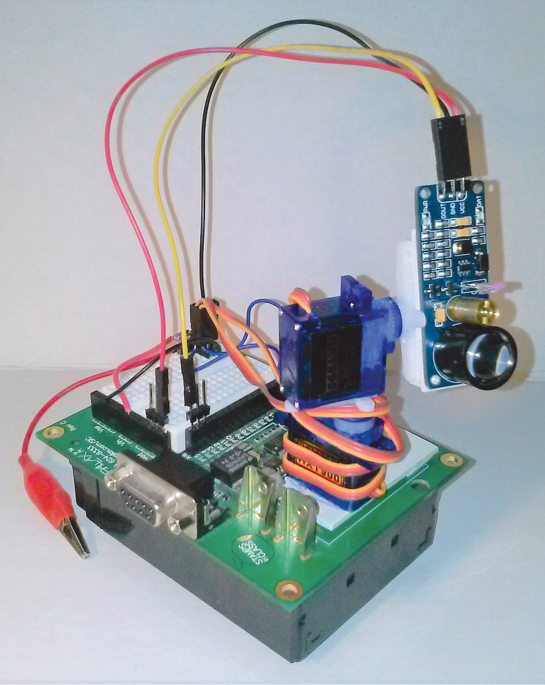
FIGURE 9.
The BS2 is quick and easy to code (Figure 10) and you display the output on its giant DEBUG screen.
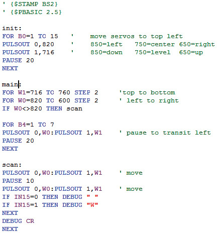
FIGURE 10.
The video here shows the scanner in operation, doing a respectable job of reproducing the word SERVO onscreen (Figure 11).
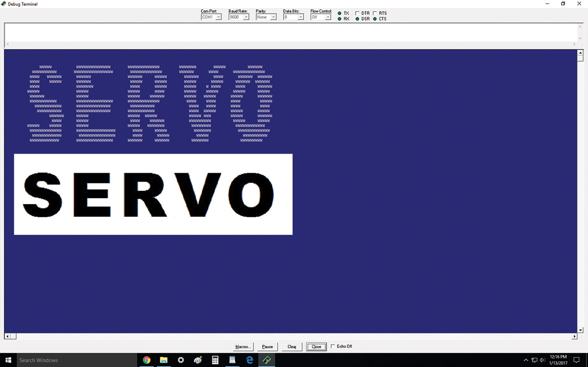
FIGURE 11.
So, this little laser sensor has plenty of other uses besides merely “obstacle detector.” These are my first experiments and I am encouraged by the results. Macrobeak, a fellow Parallax forumista, thinks it may have potential as a data link:
“I covered the module’s laser with double-sided tape and did some experiments with an external red laser. The lower bound of modulation for detection is about 18 kHz. There is no upper bound. The datasheet claims a modulated beam of 180 kHz (maybe they mean 18 kHz???). If the external laser is pulsed or modulated, the digital output at the detection data pin is nice and clean, and the module can probably be used as a remote controller or for data transmission. At a modulation of 50 kHz, it transmitted a 1,200 Hz pulse stream quite cleanly. I did not try any actual data transmission.”
It would take a bit of hacking to modulate the onboard laser, but that’s a worthy project for another day. For just $10, I think there is lots of affordable experimentation left to do. Any thoughts on what you might use this sensor for? Once again, send your ideas, thoughts, and questions to me at roboto@servomagazine.com. Until next time, keep on hacking! SV
Article Comments