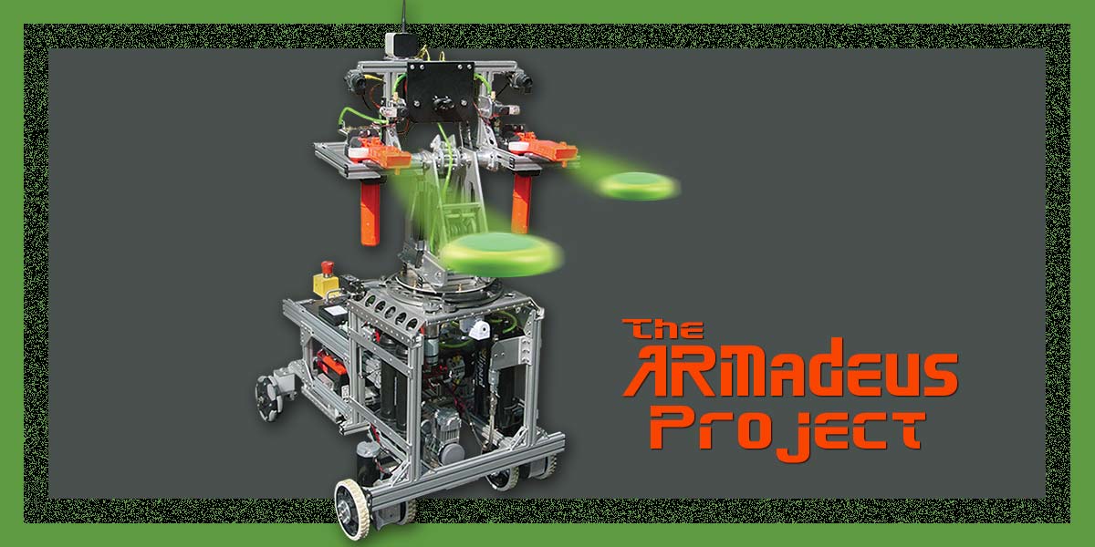
The ARMadeus Project
By James Milan View In Digital Edition
Applying the “divide and conquer” principle simplifies the building of large scale robots.
The ARMadeus Project is a series of large scale robots designed for experimenting with electrical and mechanical components. As an engineering mentor since 1995 with a local FIRST team (FRC Team 58), I’ve been conditioned to building big bots. This conditioning has heavily influenced my personal robot projects, as well. Those familiar with FRC robots will recognize many of the parts I use.
Previous ARMadeus versions were dedicated robots with various configurations of articulated arms; hence, the inspiration for the project name. With this iteration, I took a different approach. The current ARMadeus Mk. 11 model consists of a universal mobile base with interchangeable personality modules.
Main drive, power distribution, pneumatics, and actuator control electronics are housed in the base. The personality module (which easily attaches to the base) defines the primary operation of the robot, so it contains the hardware for a particular function, torso, arms, head, weapons, etc.
Not every model in the series was a roaring success. The Mk. 1 used high traction wheels in a 4WD configuration with a relatively short wheel base. It ran smoothly while moving in a straight line, but not so well when turning. Nearly every model since then now uses front wheel drive with non-powered rear wheels.
I’ve also learned the importance of managing the center of mass. Another early version weighed 165 lbs with arms reaching seven feet in the air. Unfortunately, it was prone to face-planting when its direction was changed abruptly. Newton’s first law wins every time.
Design Philosophy
I strive to build with off-the-shelf components whenever possible. When necessary, I’ll modify an existing part with the tools I have available. The only large power tools I use are a drill press and a band saw. You don’t need full machine shop capability to construct large scale, high quality robots.
I also find a cordless drill, a decent selection of hand tools, some intelligent planning, and careful measurements to be equally useful. I use ExpressPCB design software for creating low cost custom printed circuit boards (PCBs).
ARMadeus Mk. 11 uses three custom boards, a compressor control board, a level translator for shifting 5V analog sensor signals to 3.3V levels, and a four-channel 12V switch.
Since my background is electrical not mechanical, I tend to think in terms of simple mechanical components. I like to break the design process down into modular subsystems. I divide and conquer, paying particular attention to minimizing the mechanical and electrical interfaces between the modules. This module concept allows me to design, test, and optimize each subsystem independently before final assembly. I use 80/20, Series 10, T-slotted aluminum extrusions as the primary structural elements. When weight is not an overriding concern but a robust adjustable design is, T-slotted extrusions are the way to go.
Corner brackets and joining plates allow for infinite configurations. The finished product has a clean industrial look. I routinely make custom component mounting plates from 3/16” thick aluminum and 1/4” thick ABS material. Attaching to the frame is simple, and minor positional adjustments are painless.
One of the first large scale robots I built was a four foot long/100 lb hexapod using 80/20 extrusions for the frame and legs (Figure 1).
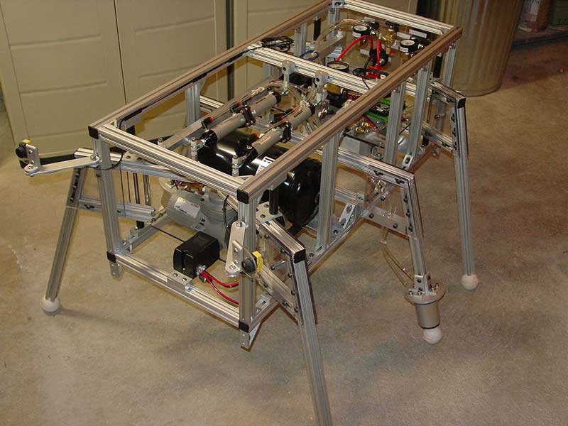
Figure 1. Pneumatic hexapod circa 2000.
The conventional tripod gate was achieved entirely with pneumatic cylinders. From that point on, 80/20 hardware became my favorite construction material.
The Chassis
The 36” x 26” chassis is made from (what else) T-slotted aluminum extrusions (Figure 2).
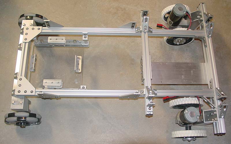
Figure 2. 80/20 aluminum extrusion robot chassis.
I’ve been using the same two NPC-2212 12V gear motors for my drive system for several years. The pair provides more than enough speed and torque — even for a 150 lb robot. The 1/2” bore keyed aluminum hubs and 6” wheels from AndyMark complete the drive motor assembly (Figure 3). The 6” rear Omni wheels are also from AndyMark.
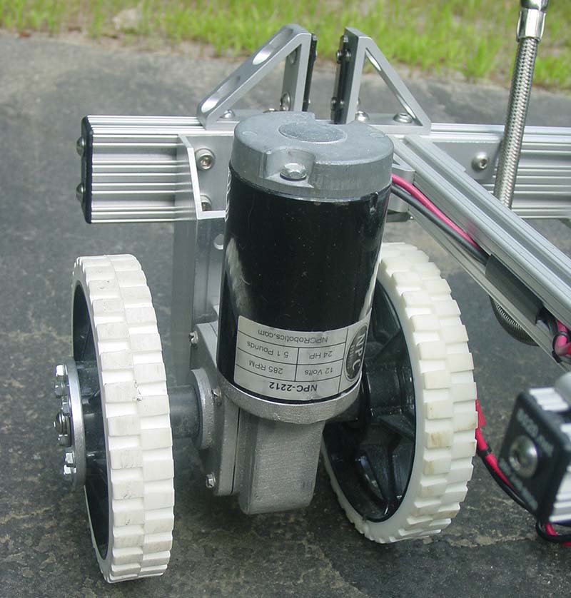
Figure 3. NPC drive motor with dual six inch wheels.
With the Viair 250C-IG compressor installed between the drive motors and the battery mounted at the rear, the completed 8” high chassis (Figure 4) accounts for nearly half of the robot’s total weight.
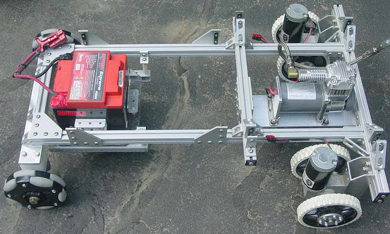
Figure 4. Robot chassis with battery and compressor installed.
This configuration with its smooth turning ability and low center of mass has proved to be very stable. I find no compelling reason to redesign the basic chassis. If it ain’t broke, don’t fix it.
Electronics Module
I constructed the electronics module using an 80/20 frame and two parallel panels of textured ABS (Figure 5). The bottom level contains a Power Distribution Panel (PDP) from Cross The Road Electronics.
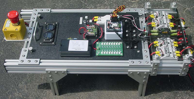
Figure 5. Electronics module.
The main battery power connects to the input of the PDP through a combination 120 amp circuit breaker/power switch. Each of the 16 PDP branch circuits has its own auto-resetting circuit breaker, ranging from 5 to 40 amps.
The robot controller and associated support electronics are installed on the top level (Figure 6).
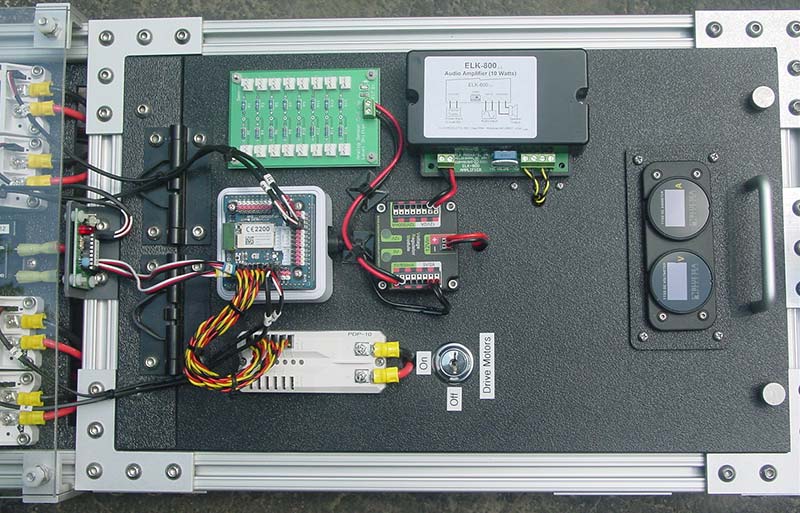
Figure 6. Robot controller electronics.
The top panel is hinged to allow access to the PDP circuits (Figure 7). Despite all the internal power connections, very little wiring is visible.
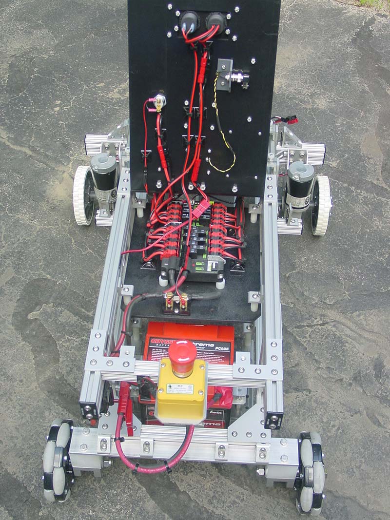
Figure 7. Hinged top panel allows easy access to power distribution circuits.
As a debugging aid and to monitor performance, I installed digital panel meters to measure battery voltage and current in real time. To cover future needs, I added a servo power module from REV Robotics. The 6V/15A device will power up to six high power servos. I always isolate the servo power to prevent surges from causing controller brown-outs.
I’ve used various electronic speed controllers (ESCs) over the years. My current favorite is the SPARK from REV Robotics. The SPARK is rated at 60A continuous current and features bi-directional limit switch inputs. The limit switch inputs allow smart motor control without tying up controller I/O pins.
I installed four SPARK motor controllers at the front end of the electronics module, along with a relay for switching the compressor (Figure 8).
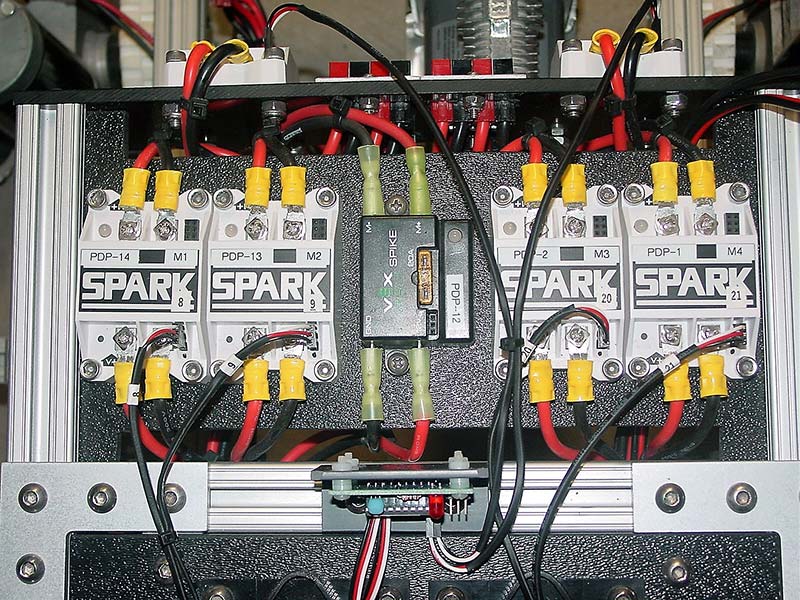
Figure 8. Front end of electronics module with SPARK motor controllers installed.
The electronics module firewall includes another two SPARK controllers for the drive motors and a breakout panel array of Anderson Powerpole connectors (Figure 9).
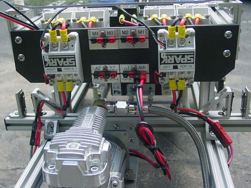
Figure 9. Drive motor controllers and connector array mounted to electronics module firewall.
The top row of connectors corresponds to the four top mounted SPARK controllers. The bottom row of connectors is for the compressor power and three auxiliary 12V/10A ports. The leading edge of the electronics module sits directly under the personality module. Individual motorized actuators (M1-M4) in the personality module simply plug into the breakout panel.
The Law of Selective Gravitation dictates that a dropped object will land where it will do the most damage. To mitigate the risk of unwanted pyrotechnics, I installed a clear polycarbonate shield over the exposed contacts of the SPARK motor controllers.
I designed the electronics module specifically with the future in mind, trying to provide the command and control resources needed for even more complex personality modules than the Mk. 11 requires.
I could have selected any number of popular programmable microcontrollers to use. I chose the EZ-Robot EZ-B v4/2. (He chose wisely.)
There is no code to be downloaded. Instead, the controller’s awesome capabilities rely on the built-in Wi-Fi capability of the EZ-B and the inherent processing power of a host PC or laptop. The EZ-B software (called EZ-Builder) also includes an extensive scripting language for creating autonomous routines.
If you haven’t done so, check out this amazing robot controller. The top electronics panel also includes a 10 watt audio amplifier to take advantage of the EZ-B speech synthesis and audio file playback features.
The EZ-B controller has 24 digital I/O pins — any number of which can be used as PWM (pulse-width modulation) outputs to drive servos or speed controllers. The Mk. 11 currently uses only nine.
I consider labeling a critical aspect of wire management — even more so as the robot complexity increases. Every motor controller is labeled with its function, PDP branch circuit number, and EZ-B digital I/O port assignment. Like the belt and suspenders redundancy analogy, PWM signal cables are labeled at both ends.
An E-stop switch is a must for a robot of this size and weight. Hitting the switch disconnects power going to the EZ-B and instantly disables all servos and speed controllers. It’s a function I’ve had to use while testing the drive system in the confines of my basement.
I added a secondary key switch to temporarily disable only the two drive motors. It’s a handy function to have for demonstrations, allowing untrained personnel to operate the robot without the fear of crashing it into nearby spectators.
Turret Module
The last section of the robot base is the turret module. It houses the hardware for storing and regulating the compressed air (115 PSI) for the pneumatics system. The turret module consists of a top turret plate and four 80/20 posts forming a tower. I mounted four 574 ml air tanks inside the tower, along with a plate for supporting the high and low pressure manifolds (Figure 10).
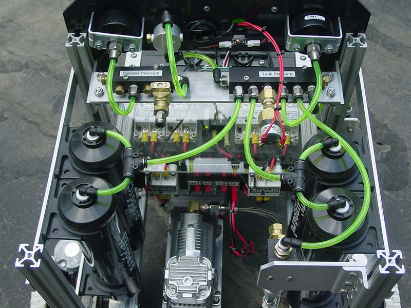
Figure 10. Pneumatic components mounted inside tower with turret assembly removed.
Pressure gauges, a pressure regulator, and a custom compressor control board are mounted on the dashboard at the back of the tower (Figure 11). The compressor control board uses a pressure switch and some simple gate logic to operate a relay, which turns the compressor on and off.
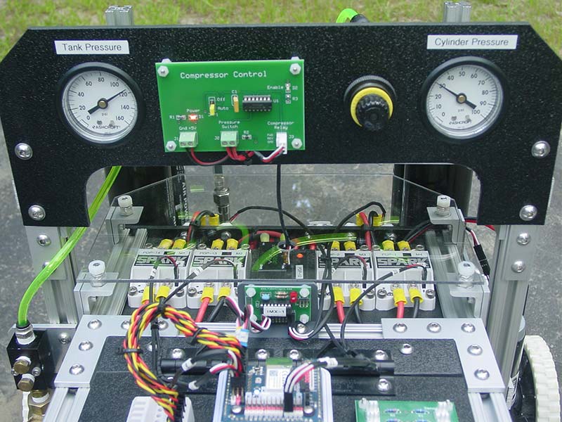
Figure 11. Pneumatics system control dashboard.
This allowed me to debug and run the pneumatics as an independent system without any connection to the main controller. It also frees up two digital I/O ports.
Not many robot builders use pneumatics. Most of my robots don’t require it either. So, the unused space was available inside the tower. What I had planned for the first personality module was begging for pneumatics. I couldn’t let that call go unanswered. Having a robot with an integrated pneumatics system already installed opens the future to some interesting design possibilities.
I consider a rugged motorized turntable the Holy Grail of robot parts. In the late 1990s, surplus 12V turntables were readily available.
These units (Figure 12) were originally designed to rotate satellite dish antennas. I have several of them which I’ve used for both torso and arm rotation. Sadly, these gems are now impossible to find.
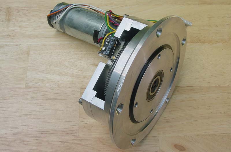
Figure 12. Surplus turntable unit.
Several years ago, AndyMark introduced a turret kit to the FIRST community. It was perfect for the type of robots I build. The key parts of the kit included a stationary turret plate, a turntable bearing, and a 240 tooth aluminum turret gear. The 300 mm diameter turntable bearing can support loads up to 330 lbs.
The kit also included a gear-driven 10-turn pot for positional feedback. A 75 RPM gearmotor with a 32-tooth pinion effortlessly rotates the turret gear. The overall design of the Mk. 11 was centered around this turret assembly. The turret gear sits at an ideal height of 24” above the ground.
I installed six 10-32 x 1.5” machine screws in the turret gear. This would form the mechanical interface between the base and the personality modules. The personality module simply drops onto the protruding machine screws and is secured with brass thumbnuts.
To complete the turret assembly (Figure 13), I added a cam to the turret gear and two limit switches at the back of the turret plate.
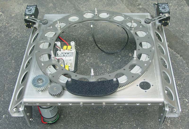
Figure 13. Turret assembly.
Rotation is limited to a 225 degree arc. I now had a rugged and stable mobile platform. The finished robot base (Figure 14) awaits installation of the first personality module.
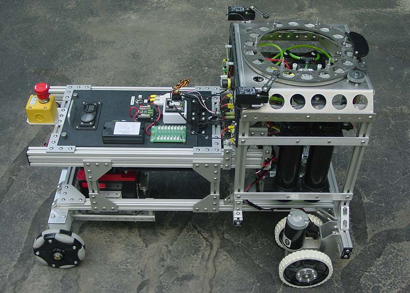
Figure 14. Completed robot base.
With the universal ARMadeus base finished, the robot needed a character infusion to bring it to life. The first step was to design a mechanical interface to the robot base. I decided to use 10” diameter 1/8” thick aluminum plates as the foundation for the personality modules.
After carefully centering a plate with the turret gear, I drilled six #10 mounting holes at 60 degree intervals around the edge of the plates, with the pre-drilled turret gear serving as a drill guide. I drilled a 3” clearance hole at the center of the plate for routing wires between the base and the personality module.
Drilling a 3” hole in aluminum with a hole saw is a lot of fun. Not! After drilling a few extra holes and adding a pair of 80/20 rails, the base plate for the first personality module was complete (Figure 15).
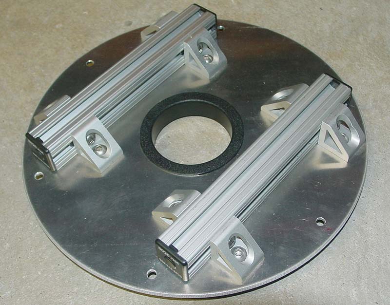
Figure 15. Base plate for first personality module.
Armed but Not Dangerous
As a change of pace from building robot arms, I decided to design something that fired projectiles and had a reasonably high ammo capacity. Airsoft and paintball guns were an option. Maybe a little less dangerous weapon system might be more appropriate.
NERF makes guns that shoot discs and darts. A foam disc launcher seemed to be the safest alternative. I bought two discontinued NERF Vortex Nitron blasters from eBay (Figure 16). If one launcher was good, then two would be even better. The launchers are capable of using 20-round magazines or 40-round drums. At the time, I had no clue as to how easy or difficult hacking the blasters would be. Challenge accepted.

Figure 16. NERF Vortex Nitron Blaster.
Opening the case revealed a daunting array of motors, switches, and small plastic parts (Figure 17). The blaster used a high speed spinning wheel to propel the foam disc — a conventional method of accelerating round objects.
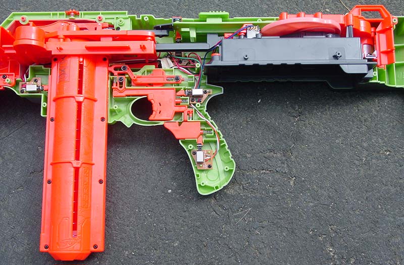
Figure 17. NERF Blaster internals.
It also used a secondary motor, a multistage gearbox, and a cam connected to a push rod. This generates the reciprocating motion that forces a disc into the path of the spinning wheel.
Besides being overly complex, it took up an inordinate amount of space. I decided that the launch motor could stay, but the complicated firing mechanics had to go.
A pneumatic firing mechanism would give me precise digital control, allowing single shot and full auto modes to be easily implemented with software.
Tediously removing screw after screw, I finally extracted the launch motor assembly and the push rod. With a few judicious band saw cuts, I saved just enough of the original outer case.
That part of the case was needed to align and secure the magazine to the launcher. After an aesthetic touch-up with some black spray paint, I mounted the hacked launch motor assembly to a 1/4” thick clear polycarbonate plate (Figure 18).
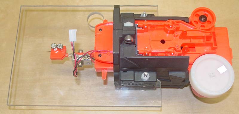
Figure 18. Extracted launcher assembly.
The push rod was modified by cutting off the cam end and installing a 10-32 threaded spacer (Figure 19).
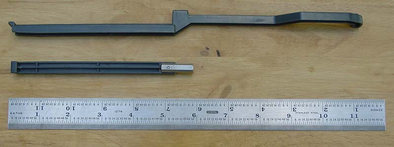
Figure 19. Pushrod before and after modification.
The rod end of a 7/16” bore 1.5” stroke single-acting pneumatic cylinder threads into the other end of the spacer (Figure 20).
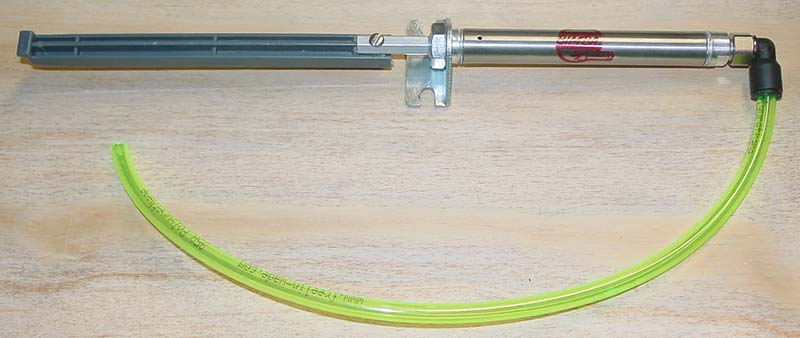
Figure 20. Modified pushrod attached to pneumatic cylinder.
After adjusting the optimal firing position, the cylinder bracket was secured in place on the 80/20 frame. The resulting firing mechanism is simple and elegant (Figure 21). At 30 PSI, the cylinder pushes the lightweight foam disc with a force of 4.5 lbs.
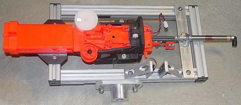
Figure 21. Completed launcher assembly.
The pair of 1/4” thick machined aluminum A-frame plates for the gun mount are one of the few exceptions to the use of off-the-shelf parts. A machinist made them for me years ago. Having a machinist friend is a good thing.
The heavy-duty plates are all that remain from a long-gone pneumatic catapult project. The plates had been collecting dust for years. I could have easily fabricated equivalent parts, but these were too good to be left wasting away.
I added 5/8” bore bearings, 12” long aluminum angles, and 4” long threaded spacers to complete the basic gun mount (Figure 22). Six lbs of heavy metal — well, aluminum — just for the gun mount frame. Overkill? Absolutely.
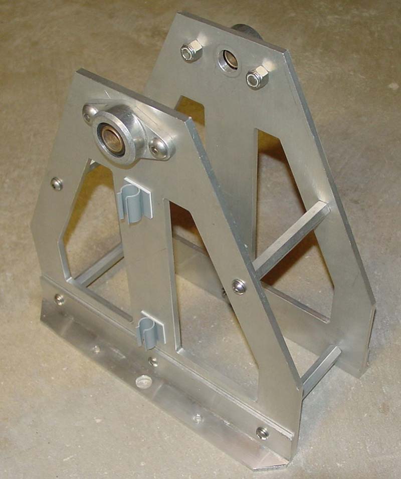
Figure 22. Heavy-duty gun mount frame.
Next, I installed a Firgelli Automation 3” stroke linear actuator from my collection. I paired it with a 5/8” diameter keyed shaft for adjusting the launcher angle between -15 and +75 degrees. Linear actuators are some of my favorite mechanical components. They are available in different stroke lengths and force and speed combinations. With simple mounting and built-in limit switches, what’s not to like?
I use them extensively for robot arms. The Mk. 7 model used six linear actuators for the torso, shoulder, and arm movement.
There was some empty space at the front of the gun mount. Since Nature abhors a vacuum, I installed a pair of eight ohm speakers there (Figure 23).
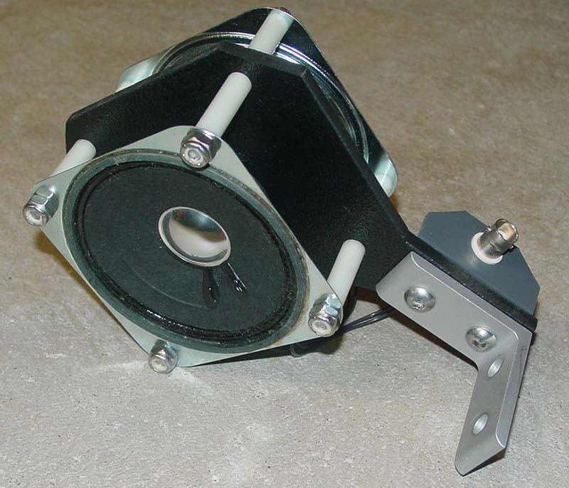
Figure 23. Speaker assembly.
The completed launcher assemblies are now ready to be installed to the gun mount shaft (Figure 24). I added two additional 80/20 posts and a top rail.
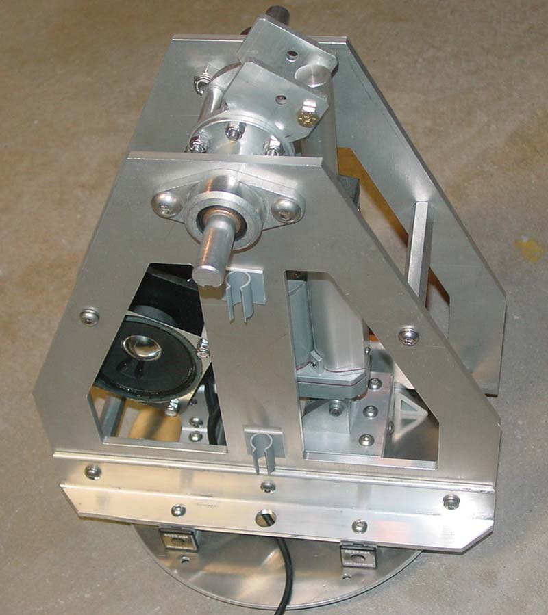
Figure 24. Gun mount with linear actuator and speakers installed.
The posts provide convenient mounting locations for the pneumatic solenoids, while the top rail supports a video transmitter and target monitoring video cameras at each end in-line with the launchers.
I added two ABS panels to the top rail for more electronics. The front panel has two 12V LEDs wired in parallel with the launcher motors, providing visual warning indicators that the motor is spinning and ready to fire (Danger, Will Robinson!; Figure 25).
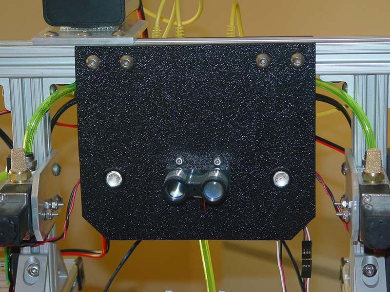
Figure 25. Front panel with LED warning lights and LIDAR-Lite rangefinder.
The launcher motor spins in excess of 15,000 RPM. I also connected a LIDAR-Lite rangefinder to this panel. The rear panel contains a four-channel video multiplexer, a custom four-channel 12V/1.5A switch for energizing the pneumatic solenoids, and a three-axis accelerometer for measuring the launcher tilt angle (Figure 26).
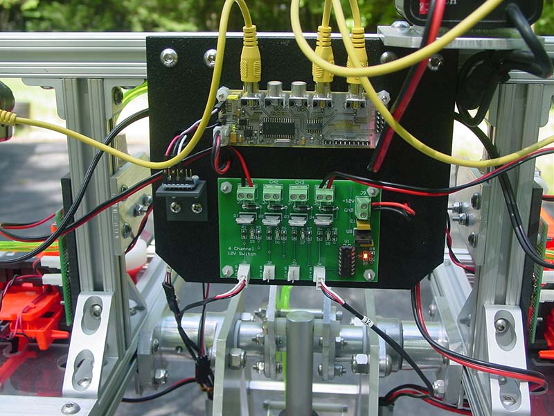
Figure 26. Rear panel with video mux and solenoid switching electronics.
It’s Alive
The launchers shoot the discs about 60-70 feet. The design of the disc limits the range more than the motor speed. The more impressive feature is the rate of fire. The fast-acting pneumatics can simultaneously empty both 20-round magazines in about SIX seconds, flooding the target area with foam projectiles.
The 30 lb personality module (Figure 27)
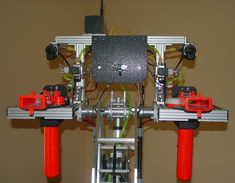
Figure 27. Completed personality module with dual disc launchers and 20-round magazines.
mates perfectly to the turret gear (Figure 28).
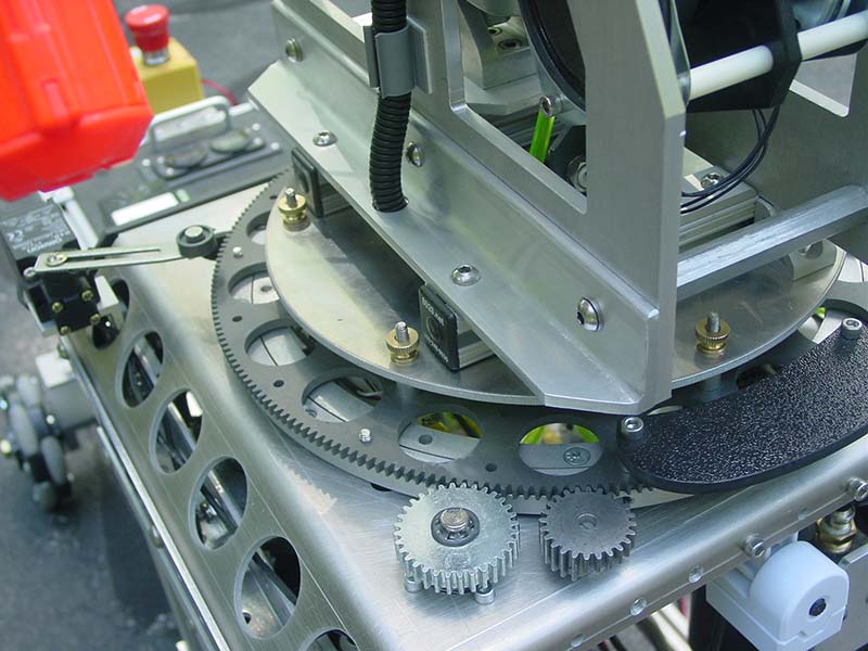
Figure 28. Close-up of mechanical interface between the personality module and the turret gear.
The 140 lb ARMadeus Mk.11 (Figure 29) functions as expected. The universal base and turret interface designs work well.

Figure 29. Completed ARMadeus Mk. 11 robot.
The modular design and test concept was very successful, allowing the entire robot to be quickly disassembled into five sections for transport (Figure 30).
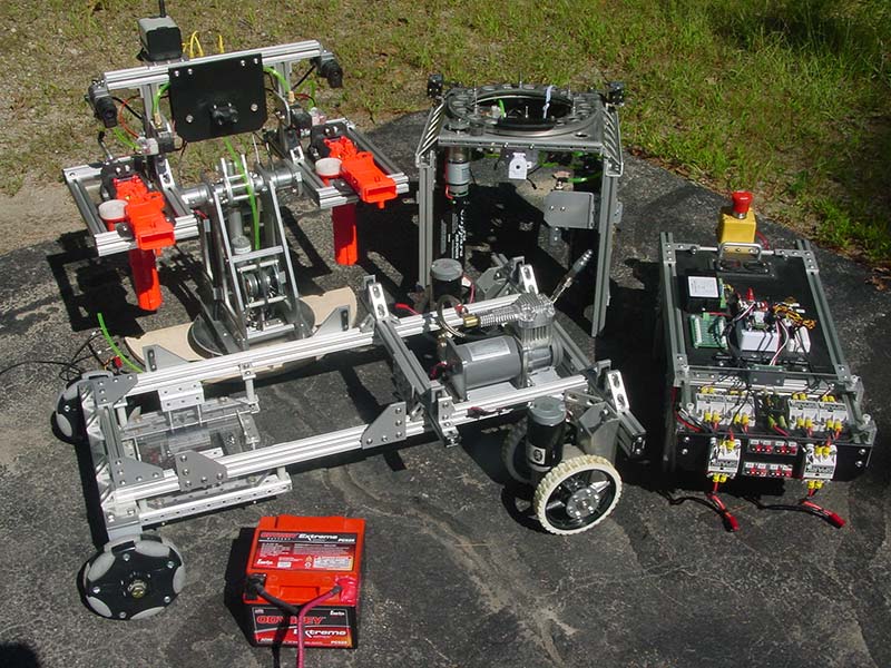
Figure 30. ARMadeus disassembled and ready for transport.
So, what’s next? I definitely want to tinker with the current model and explore the power of the EZ-B software before the next build. NERF has a new line of guns that shoot miniature foam golf balls at 100 fps. Hacking them would be even simpler than the disc blasters. Maybe, it’s time to take foam-based weaponry to the next level.
I also have a number of body parts (pan/tilt head, arms, grippers) from the remains of previous robots. If nothing else, the Mk. 11’s predecessors served as willing organ donors. Additionally, there are a number of multiple DOF arm designs I’d like to try.
When I do decide to construct a Mk. 12, I won’t have to start from scratch. SV
Sources
Mechanical, electrical, pneumatic robot parts
andymark.com
Aluminum T-slotted aluminum extrusions
8020.net
NPC motors
robotmarketplace.com
Robot controller
ez-robot.com
Robot electronics
revrobotics.com
Air compressors
viaircorp.com
Linear actuators
firgelliauto.com
Digital panel meters, Anderson connectors
powerwerx.com
Mechanical and pneumatic parts, fasteners
mcmaster.com
PCB Design Software
expresspcb.com
Article Comments