Ultrasonic Radar Refresher — Part 2
By Dan Harres View In Digital Edition
If you read Part 1, you know how a piezoelectric ultrasonic transducer works. Now it’s time to come up with the circuits that will drive such transducers and convert their received voltages to useable signals.
Transmitter Circuits
First, we need to drive the transducer to generate the proper frequency. As mentioned last time, a piezoelectric transducer has a natural frequency determined by its dimensions and its material. The device is resonant and — if we are to get useful acoustic vibration from it — we need to operate the transmitter at or very near to this natural frequency.
With any driver circuit, we need to know what our load looks like in terms of the voltage, current, and impedance requirements. Maximum drive voltages for these transducers are typically on the order of 20V, but we need to be a little careful in how we read such a specification. If the datasheet says 20 Vrms (root mean square) maximum, then a 0V to 40V square wave would satisfy this limit. On the other hand, if the datasheet says 20V peak-to-peak, then our square wave generator should be 0V to 20V.
By the way, the transducer (being a highly resonant device) will filter out all but the fundamental frequency, so it doesn’t matter if our generator produces a sine wave or a square wave. In most applications, the square wave is easier to generate, so we’ll use that as our wave shape.
For the remainder of this article, a 30V source voltage will be used with the understanding that the actual voltage needs to be tailored to the particular transducer used.
The Ultrasonic Transducer Looks Like a Capacitor to the Driver
Piezoelectric transducers electrically look like a capacitor. The capacitance value should be given on the datasheet. Typical values are 2,000 pF and 3,000 pF. Since the device is useful to us only at its resonant frequency, we can immediately determine the reactance as:
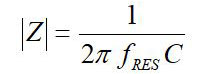
where f RES is the transducer’s resonant frequency (for example, 40 kHz or 25 kHz). So, for a transducer with a resonant frequency of 40 kHz and a capacitance of 2,400 pF, the device looks like a 1.65 kΩ resistor. A 30V pulse across the transducer will therefore result in a current of about 18 mA through the device.
Where Do We Get the High Voltage?
To produce a 30V square wave, we need a DC power source that generates at least 30V output. So, where do you find such a voltage on most robots or other small vehicles? Fortunately, it’s not hard to build a circuit that can boost the 3.3V or 5V on a board to 30 or more volts. To see how this is done, take a look at Figure 1.
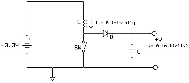
Figure 1. Basic boost circuit.
The circuit is simple: an inductor, a capacitor, a diode, and a switch. In most cases, the switch is a transistor, controlled by some external as-yet-undefined additional circuit. So, how does this work?
To start, the switch closes (Figure 2). Assume that initially, the inductor has zero current and the capacitor has zero voltage.
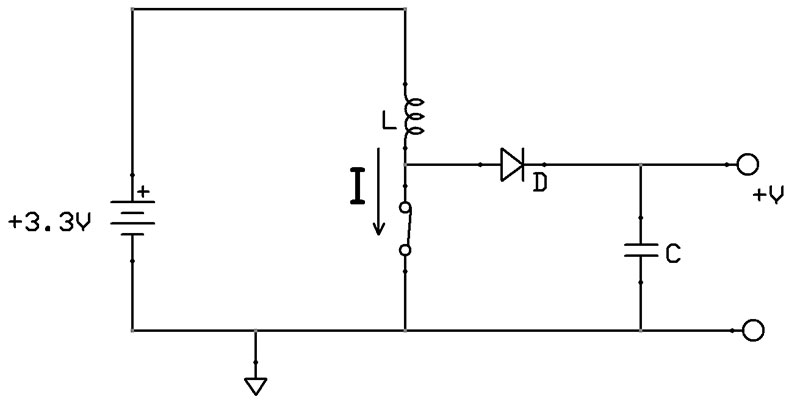
Figure 2. Boost circuit charging.
With the diode reverse-biased, the circuit really is just the inductor connected across the +3.3V (or whatever the low voltage is that we’re using as the energy source). The current through the inductor increases at the rate:
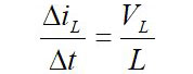
where VL is the DC supply voltage (3.3V in the example).
At this point, all the inductor current is flowing through the switch. After holding the switch closed for some period, TCLOSED, the switch is then opened. At this point, the inductor current has risen to the value:
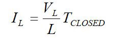
Now things get interesting. When the switch is opened (Figure 3), the inductor current is no longer able to take the switch path, but the inductor current must keep flowing.
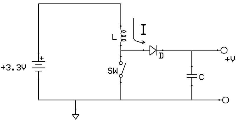
Figure 3. Boost circuit releasing its energy to the capacitor.
If you’re not used to working with inductors, they are the dual of a capacitor. Whereas a capacitor is perfectly willing to instantaneously change its current but tries to maintain whatever voltage is already across it, the inductor is perfectly willing to instantaneously change the voltage across it, but wants to maintain the current flowing through it. In this case, the inductor will increase its voltage until it finds a new path for its current — which happens to be through diode D.
In fact, this is how the ignition on your car works. If we replace the capacitor in Figure 3 with a spark plug, we have an automobile ignition system. In that case, an inductor — referred to as the coil — is charged by momentarily closing a switch that shorts the coil across the car’s battery. When the switch is opened, the built-up current has to go somewhere.
The inductor voltage at the opened switch rises until it’s high enough to “jump the gap” of the spark plug. This provides the inductor current a path back to the car’s “ground” and — in the process — creates a spark within the engine cylinder, igniting the air-gas mixture in the cylinder.
Okay, back to our boost circuit. Remember that we assumed an initial capacitor voltage of 0V. So, when the switch opens, the inductor voltage at the inductor/diode/switch junction need rise only a few tenths of a volt for the diode to start conducting and the capacitor to start charging.
At this point, the capacitor is charging as the inductor discharges (that is, the energy stored in the inductor during the closed switch is transferred to the capacitor during the open switch).
This closed-switch/open-switch cycle repeats, with the result that the output voltage, +V, rises higher and higher. When it finally reaches the desired high voltage, we’ll need to adjust the switch “on” and “off” times to maintain the output at that voltage. Wait a minute — just how do we control the on and off time?
Fortunately, there are integrated circuits that are designed to do exactly that. If you do a search on the term “boost” at an IC distributor’s website, you should find lots of choices. In this case, we are dealing with a need to produce less than 100 mA at a 30V output; there are lots of boost regulator ICs capable of handling that.
Because the required current is relatively low, physically small and inexpensive inductors and capacitors should suffice. The boost control IC datasheet will give more particulars about just what these components should be. Refer to Figure 4.
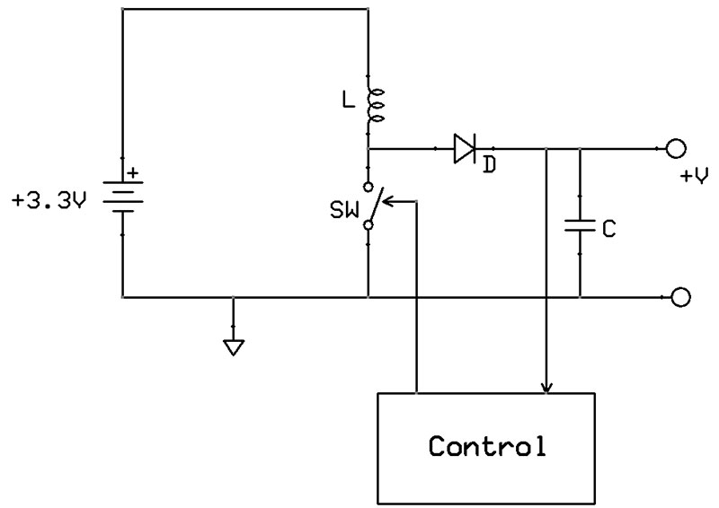
Figure 4. Complete boost circuit diagram.
Driving the Ultrasonic Transmitter from the High Voltage
Okay, we can generate the high voltage with relative ease. So, how do we take the 3.3V or 5V signals from our microcontroller or other device that generates the transducer’s frequency signal and use that to turn the high voltage on and off? What we are looking for is a circuit like the one in the Figure 5 block diagram.
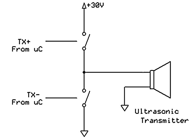
Figure 5. Ultrasonic transmitter block diagram.
Basically, we just want two fast switches that can alternately turn on using the microcontroller signals labeled TX+ and TX-.
The bottom switch is straightforward: An NPN transistor (Figure 6) will switch on when its base resistor is presented with the three to five volt signal from the microcontroller.
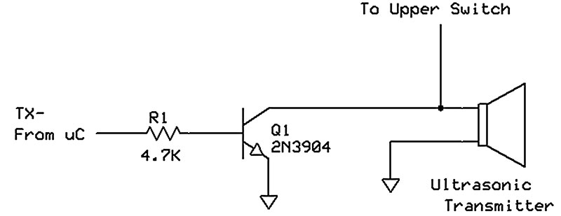
Figure 6. Bottom switch for ultrasonic driver.
Its collector can withstand the high voltages while isolating the microcontroller from such potentially catastrophic voltage.
The high-side switch is a little more involved. A PNP transistor makes a good complementary switch, but the base voltage of such a transistor will always be within one diode drop from the high voltage, and therefore cannot be driven directly by the microcontroller.
Instead, an additional common-base NPN stage is added to interface between the microcontroller and PNP output (Figure 7). Note that Q3 is turned on when TX+ goes low.
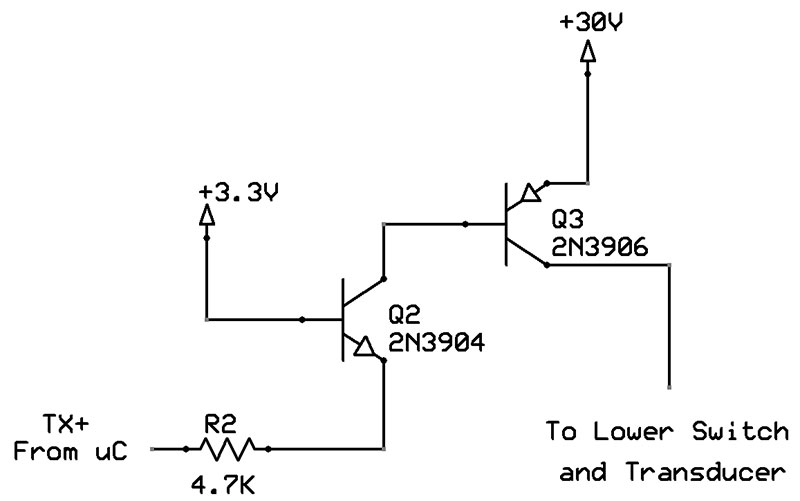
Figure 7. High-side transducer driver.
Putting these together gives the transmitter drive circuit of Figure 8.
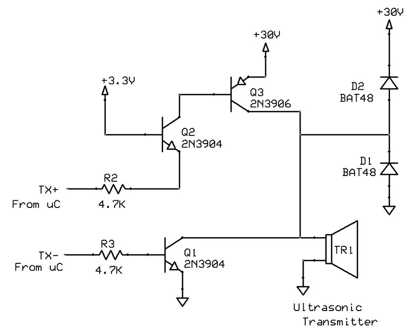
Figure 8. Complete ultrasonic transmitter circuit (receiver transducer and circuit separate).
Note the following things about this circuit. First, diodes D1 and D2 have been added across the transmitter. Neither of these will turn on unless the transducer voltage goes one diode drop higher than the +30V supply voltage or one diode drop lower than ground! Why would we need these?
It turns out that when we drive the transducer at its resonant frequency, then suddenly stop changing the voltage, the transducer diaphragm continues vibrating (remember this is a resonant contraption).
As the diaphragm flaps around, it actually produces voltage (it’s a piezoelectric crystal), so it can produce voltage well above +30V or well below ground as it rings down.
Such a situation probably won’t wreck your circuit, but the diodes are there to make sure you don’t have to test that theory.
The second thing to note about this circuit is that it is transmit only. To receive the ultrasonic echoes, a second transducer is used strictly for receiving. This transmit-with-one-transducer/receive-with-a-second-transducer is the configuration used in most hobbyist setups.
Since ultrasonic transducers theoretically transmit and receive, some transducers are sold as “transceivers;” that is, devices capable of either mode. Since the transmit and receive periods are usually set up to occur at mutually exclusive times, having a single transducer to handle both functions is entirely feasible. Figure 9 is such a transceiver circuit.
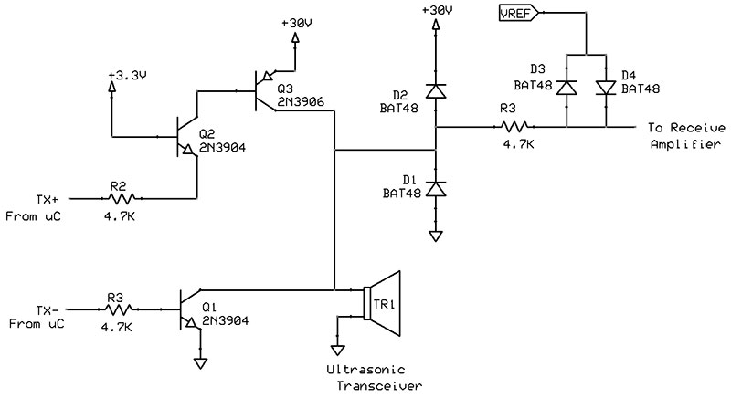
Figure 9. Ultrasonic transceiver circuit.
The trick here is to be able to deliver high voltages during the transmit period without wiping out low-voltage circuits in the receive amplifier section. This is made possible by the diodes D3 and D4 along with R3, with the back-to-back diodes connected to VREF, a voltage midway between the 3.3V (or whatever the supply voltage is for the receiver) and ground.
Also, when the circuit is to be in the receive mode, there needs to be a means of putting the transmit drive circuit into a high impedance state. Fortunately, this is already built into the transmit drive. When TX+ is high and TX- is low, both sides of the transmit drive circuit are off.
Frequency Generation
Most microcontrollers are quite capable of accurately producing the 25 kHz, 40 kHz, or whatever other frequency is needed for transmission. One thing to keep in mind when doing this is that as with any half-bridge (totem-pole) circuit like the ones in Figures 8 and 9, it’s good practice to first turn off the active output transistor before turning on the other output transistor, since turning one on simultaneously with turning the other off may result in a momentary short across the high voltage.
Wrap-Up
These first two articles have been all theory: first about ultrasonic transducers; and then about the electronics needed to drive those transducers. The next article will show the actual circuits, plus an announcement of a new and unique approach to precision ultrasonics. SV
Article Comments