Tips for Selecting DC Motors for Your Mobile Robot
By A. J. Neal View In Digital Edition
When building a mobile robot, selecting the drive motors is one of the most important decisions you will make. It is a perfect example of an ideal world meeting the real one. This article will cover some of the basic physics and the rules of thumb I use to select DC drive motors for mobile robots. Before you can select your motors, you’ll need to know what characteristics the robot you want to build will have. How large will it be? How much will it weigh? How fast will it move? What terrain will it operate on?
Once you have an idea of what your robot will look like, start with some basic physics to get an idea of your motor requirements. After you have calculated your requirements, you can further define the motors that will best suit your robot. Finally, you can start looking for motors that will meet your needs armed with realistic specifications and an understanding of how they relate to your robot’s performance and capabilities. In most cases, you will not find the perfect motors for your robot and you will need to make some tradeoffs in order to make your final motor selection.
Let’s start at the beginning with some definitions.
What exactly is a DC motor?
A direct current (DC) motor consists of a set of magnets, rotor coil, and commutator. When you apply current to the rotor coil, it will turn into an electromagnet and repel the magnets. The commutator causes the current in the rotor coil to switch polarity as it rotates. This polarity switch causes the rotor coil to repel the magnets and generate continuous torque. Speed in a DC motor is proportional to the voltage applied to the rotor. The power produced by the motor is proportional to the voltage multiplied by the current. When working with DC motors, it is essential to remember the relationship between power, voltage, and current.

Another key relationship is:

This means that in order to increase the power output of the motor, you can increase the voltage rating or increase the current. For example, a 12 volt DC motor can supply the same power as a six volt DC motor, but at 1/2 the current. This is important because most components are limited by the amount of current they can carry. If your robot will be extremely heavy, you may even want to look at 24 volt DC or even 90 volt DC motors. One of the trade offs for the higher voltage is safety. It is hard to shock yourself at 12 or 24 volts, but 90 volts can cause shock and possible injury. Another key property of DC motors is that the speed is controlled by changing the voltage. When sizing a DC motor, we will use the rated voltage of the motor. This is the maximum voltage the motor is designed to handle. There are several different types of DC motors to select from. In most cases, I use brushed DC gearhead motors. Gearhead motors have a gearbox installed as part of the motor. This gearhead is a gearbox attached to the output shaft of the motor. A few other types of DC motors include brushless and stepper motors.
Gearboxes are sometimes called reducers because the output shaft of the gearbox will be less than the output shaft of the motors. The reduction in speed results in an increase in torque. This is a good place to start because most DC motors have output shaft rpms (revolutions per minute) of several thousand and very little torque. Using a gearbox will reduce the shaft speed and increase the torque.
When selecting DC motors, you must understand some of the basic physics that will affect your robot. Some of these physics concepts you should understand are force, weight, mass, torque, acceleration, and velocity, and the relationships between them.
What is Weight?
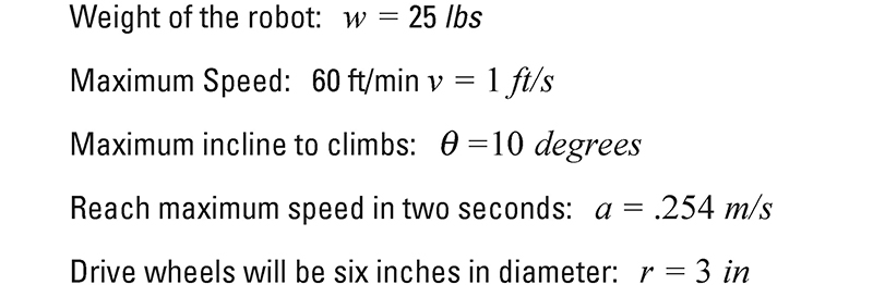
Most of us have talked about weight all of our lives. We know that every object has a weight. But how is weight defined in the world of physics? Weight is actually defined as the force due to the acceleration of gravity on a body. On Earth, we normally use 9.8 m/(s^2) or 32 ft/(s^2). If you are planning on building a robot to roam around on the Moon or Mars, the acceleration value will be different. This means your robot’s weight differs depending on what planet it is roaming around on. Let’s take a robot that weighs 25 lbs here on Earth. Remember, pounds are the English unit of weight, not mass. Each of the engineering equations we will use later has specific units. It is important to watch out for this. Nothing would be more embarrassing than sending a robot to Mars because weight was used when you should have used mass. Figure 1 is a simple free body diagram of a simple robot with two front drive wheels and a rear caster.
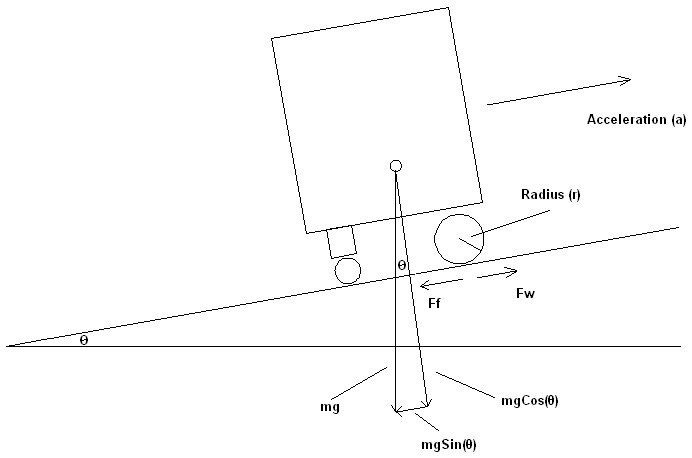
FIGURE 1.
This demonstrates the various forces that will act on the robot. We will start by examining the effect of gravity on our robot.
What is force?

Most commonly written as:

On the free body diagram, the key forces are:

This is the force pulling the robot down toward the center of the Earth due to gravity.
On a free body diagram, the force of weight is broken down into its two components.

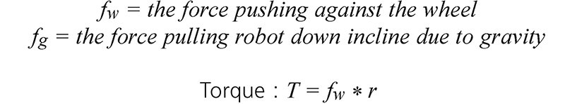
The force is pulling your robot back down the incline and must be overcome by your drive motors. The greater the angle of incline, the greater this force will be. The incline a robot is trying to climb makes a significant difference in the torque required from your drive motors.

This force is holding your robot onto the incline. This force is required along with friction to allow your robot’s drive wheels to push the robot forward up the incline. We will ignore friction, because the force of friction is what the drive wheels need to push to move the robot forward.
On our free body diagram, torque is the force at the edge of the drive wheels pushing our robot up the incline.
But What is Torque?
Torque is the measurement of the force applied to rotate a body around a particular axis. In a mobile robot, the body will be the wheel and the axis will be a motor shaft. Torque is measured in units of force and distance, for example in-lbs. What does this mean? If you have a torque of 6 in-lbs, you can expect 6 lbs of force, one inch from the shaft of the motor. In our case, our drive wheels are six inches in diameter. This means that the force is applied three inches from the drive motor. We could expect 2 lbs of force to be applied by the wheel to the ground. As you will see, many of these values come in a variety of units. Some popular measurements of torque are ft-lb (foot-pounds), oz-in (ounce-inches), and Nm (Newton-meters). Some units will be in English units and some will be in metric units. Values will need to be converted to metric before plugging them into the equations. In most cases, these resulting answers will need to be converted to English units in order to determine what motor to order from most suppliers.

Finally, velocity is the speed at which our robot will move up the incline and acceleration represents how fast our robot will reach the desired velocity.
How does acceleration relate to speed (velocity)?

Now that we understand the forces acting on our robot, we can begin the process of sizing the drive motors.
To determine what size motors we need for our robot, we will need to define the following:
From our free body diagram, we will focus on the forces working in parallel to the inclined surface. Let’s also assume that our robot will start from rest and need to accelerate up the incline to full speed.
In physics, all forces must balance which gives the equation:

If your robot is moving at a constant speed, the sumation of all forces will equal zero.

To properly size our motor, we will focus on the situation where the robot is accelerating from rest to full speed. This is where you want to size your motors to be large enough to get the job done. The torque required to get your robot moving can be much greater than keeping it in motion. In this case, the sumation of the forces acting on our robot will equal the total mass multiplied by acceleration. I usually accelerate my robot to full speed in one second or less in the calculations.

Finally:

We must convert weight to mass in metric units:

Next, we convert radius from three inches to meters.
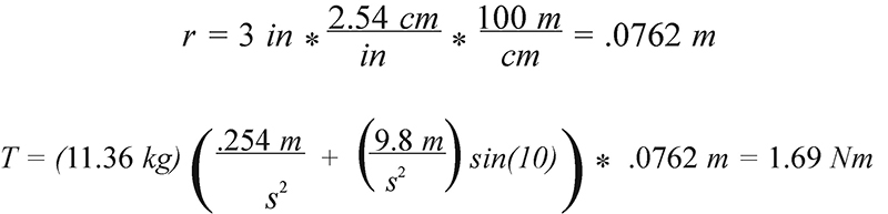
Most of the motors I have worked with define torque in in-lbs or oz-in. We will convert to in-lbs:

This is the total torque required to drive the robot. Since we are using two drive motors, we can divide this in half.

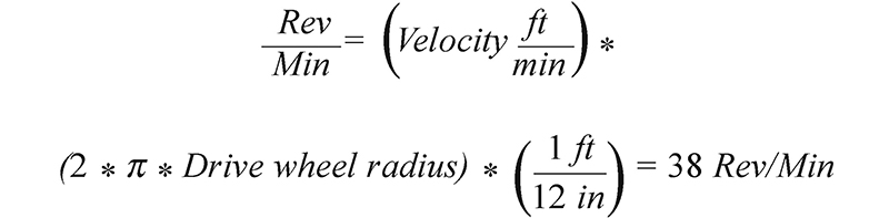
Next, we will determine how fast in rpms the motor will need to turn.
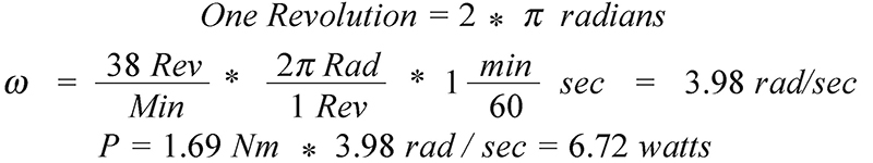
Finally, to determine how much power the motors are required to supply, the following equation should be used:

Angular velocity is measured in radians per second.
If looking at motors with English units, power will be specified in horsepower.
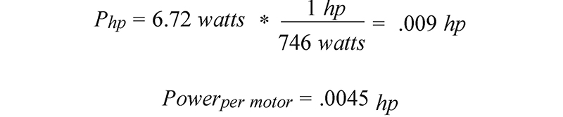
These values are in a perfect world. Most robots do not get to operate in a perfect world, so you will need to account for the losses in the DC motor and inefficiencies in the gearhead. I usually assume the losses are 50% or greater. Find a motor that will deliver at least twice your requirements or greater; this is a good rule of thumb.
I went to Grainger’s website (www.grainger.com) to see if I could find a motor to meet our specifications. The motor specifications usually include the full load current, rpm, and torque. These are the maximum values the motors are designed to operate at. I was able to find one motor that looked like it would meet all of the requirements; the full load torque of 25 in-lbs and rated for 41 rpm. I then noticed it would cost more than $150 for each motor. Spending $300 for drive motors would bust my robot budget, so I decided to keep looking. I was able to find two more motors that were close to our calculated requirements: one with an output torque of 10 in-lb at 50 rpm and the other with an output torque of 20 in-lb at 25 rpm. These both used the same motor with a different gearhead and these motors were less than $50 each. This is a much more reasonable price. Our ideal robot would have at least 16 in-lb of torque per motor at 38 rpm. I decided to go with the motor that would supply 10 in-lb of full load torque at 50 rpm. This would give the robot plenty of speed, but might require the final weight to be reduced. Trading a little weight to save $200 seemed like a good deal to me. I also know that my specification is for a “worst case” situation and my motors will probably handle a 25 lb robot just fine.
Once you have selected your motors, you can plug them back into your equations and see how your choice may affect your final robot design. Again we start with the equation:

A little more algebra takes us to:
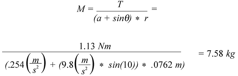
If we multiply this value by two for each drive motor and divide by two for our safety factor, then convert our kg value to pounds, we end up with a 17 pound robot. You can probably exceed this value by four or five pounds without much concern, but you know that you will not be able to build a 70 pound robot using these motors and meet your performance requirements.
A better way to look at the performance you can expect from a DC motor is the speed-torque curve. One nice thing about DC motors is that most of the relationships are linear. So, a graph that shows the relationship between speed, current, and torque is easy to develop. You only need to have to a few values. These are No Load Speed, No Load Current, Stall Current, and Stall Torque. You already know the stall speed is zero.
Figure 2 is an example of the graph from a motor for a larger robot. The following values were supplied by the manufacturers specification sheet.
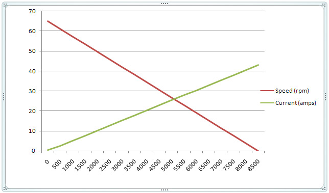
FIGURE 2. Torque oz-in, rpm graph.
The No Load Speed is 65 rpm, the No Load Current is .63 amps, and the Stall Torque is 8,500 oz-in. The motor has a maximum efficiency of 66%. We would like the motors to operate at about 1,000 oz-in and around 55 rpm. I was able to quickly generate a speed-torque curve in a spreadsheet. From this graph, I could see the robot will need to supply about five amps per motor. If possible, I like to stay on the lower 30% of the speed–torque curve. Stalling a DC motor can result in a much shorter operational life. If you are using a gearhead motor, it can also destroy the gearhead.
Other Considerations
During the initial selection of the motor, we assumed that there was enough friction between the wheel and the surface so there is no slip. This is actually a bad assumption. Most wheels will spin when the robot is started at full speed on a slicker surface. In some cases, this can be a real problem. One solution to this situation is to select different wheels. Or, a better solution is to ramp up the motor speed instead of starting at full speed.
When selecting motors, another key consideration is the fine print on the specification sheet. A motor may be capable of supplying much more torque than the gearbox or bearings can handle. On some gearheads, you will see a rating for overhung load. This is the maximum weight the manufacturer recommends you support from the output shaft. Another consideration is the torque limit of the gearhead. This can be less than the motor can actually supply. If you exceed this value for any length of time, you could destroy your gearhead. Better motors use better gearheads. One way to tell the quality of motor you are using is by the noise it makes when running. The louder the motors, the less efficient the gearhead motor is. High quality gearheads are very quiet, but they are also expensive.
Battery selection is another key aspect of getting the most out of your drive motors. The right battery will need to supply current for the desired robot run-time. Batteries are specified with two key values: voltage and amp-hours. An amp-hour is defined as the amount of time — in hours — the battery will supply one amp of current. To get an estimate of how long your robot will run on a given battery, just take the battery rating and divide it by the average current draw of your robot. Do not forget this should be for the entire robot, not just the drive motors. For example, my robot has a 12 amp-hr battery. My robot normally draws less than two amps, so I expect to get five to six hours of run-time with a fully charged battery. To get a ball park of the power your batteries will need to supply to your motors, you can use the relationship between power, voltage, and current.
We’ve completed an exercise in basic motor sizing for a mobile robot. In most cases, you should shoot for exceeding your calculated requirements by two or three times. If you purchase undersized motors, it usually costs more than purchasing oversized motors because you will end up buying a second set of motors that are large enough to supply the power you need.
The free body diagram and basic physics is a great place to start when sizing a motor in any situation. Our example was very simple; you can always add more detail to the free body diagram. This can help you answer other questions. For example, how much of an incline can your robot handle before it tips over?
If you want more information, a great source of information is the book Mobile Robots — Inspiration to Implementation by Joseph L. Jones and Anita M. Flynn. The Zagros Robotics lab notes section also includes information on many topics, including DC motor selection. (www.zagrosrobotics.com). SV
Article Comments