Servos the Right Way
By Myke Predko View In Digital Edition
How to get the most out of servos in your applications
This article started off as a rant that originally began with me looking at a number of robot and other projects that had the radio control servos (like the one in Figure 1) connected incorrectly, or else demonstrated that the designer didn’t understand how to best create control signals to them. Most servo circuits I see risk damaging the controller that is driving them, or force the software developer to make compromises in their code to drive the servos. With a better understanding of servo technology, you can implement servos in your application that work reliably, pose no risk to the controller (as well as the PC used to program the controller), and eliminate the need for considering servo operation in your application code.
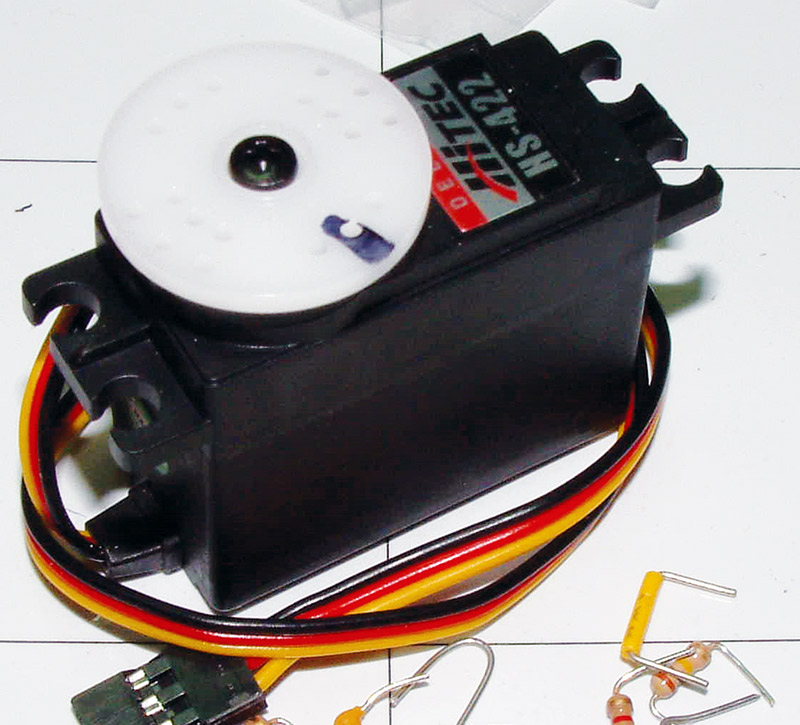
FIGURE 1. A basic servo: the Hitec HS-422.
In this article, I’m going to focus on the electrical interface from the power, as well as the programming perspectives. I am not going to discuss how to bolt servos into a project or how to select the best one to use based on the mechanical parameters of torque output, movement direction, speed and angles, or drivetrain gear type.
When I wrote this, I used the Hitec HS-422 general-purpose servo which is easy to work with, low cost, very reliable, and available from multiple distributors. The important characteristics of the servo are:
- Operating Voltage: 4.8V-6.5V
- Control System: 600 µs to 2,400 µs pulse every 20 ms for 180 degrees of rotation
- Idle Current Requirement: 8 mA (no pulses sent to the servo)
- Active Current Requirement: 150 mA
About RC Servos
Radio control servos are really built from what can only be considered ancient technology; the first servos that provided the capabilities of the ones used today were introduced in 1965 for use in model aircraft. In 1965, integrated circuits had only just been introduced; the first microprocessors were still a number of years away; battery technology consisted of disposable carbon cells (alkaline batteries weren’t available until the 1970s); rechargeable Nickel-Cadmium batteries were known as “NIFE” cells, and weren’t available to consumers in the “AA” form factor until 1970. The technology of the time is important to keep in mind when you are planning on using servos, as it affects how you interface to them.
The first misconception that many people have about servos is that they are digital devices. They are actually analog devices. This is confused by the name that is applied to the servos. They are called “digital proportional” which is really marketing speak to make servos sound like modern devices, and not something that came out when the Beatles were still playing live shows.
In regard to the control signal passed to servos, I’m sure that you’ve seen something like Figure 2 showing that the length of the pulse which is sent to the servo is used by the servo to set its output position.
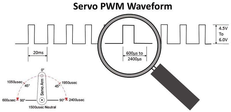
FIGURE 2. The servo pulse stream with timings.
The pulse length is a continuous function; it is not broken into discrete steps (as in many software representations, including one of the Arduino libraries that I use in the example programs discussed below). This continuous output is both a blessing and a curse.
Being an analog device, servos are not completely accurate nor are they precise. If you have two servos, chances are the same pulse width will not set both of the servos to the same position, and if you move them to new positions and then back, you’ll find that they may not return to exactly the same place.
This was compensated for in radio control models with “trim pots” which minutely varied the timing of the signal sent to the servos to ensure the model would return to a neutral position. I’m pointing this out because it can be an issue in applications that require very precise and accurate actuator movements. If that is the case, then you should be looking at stepper motors or more modern servos which provide much more accurate positioning.
Servo Test Circuits
I’m sure that by now you’re starting to get bored with my prattling on, so let’s change the pace and start building some circuits and gain some empirical knowledge regarding servos.
The first bit of wisdom that I want to impart to you is the need for a servo connector that you can plug into a breadboard. Servos require header pins that are at least 1/4” (6 mm) to 3/8” (9 mm) in length, and consist of three pins that are on 0.1” (2.54 mm) centers.
As I can never reliably find headers that are long enough on both sides, I usually make my own from soldering together the short ends of two standard printed circuit board (PCB) headers as shown in Figure 3.
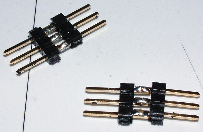
FIGURE 3. Solder two three-pin headers together to make servo adapters.
To lock everything together, I usually put a couple of drops of Weldbond over the solder joints. Over the years, I have probably made a hundred of these things; they are incredibly useful to have, and people are always stealing them from me.
Another pearl is that if you are using a wheel or a multi-armed horn for output, remember to mark one position with a Sharpie™ so you’re not trying to decide whether or not something happened with the servo.
Servo Tester
A useful thing to have in your servo toolbox is the simple servo tester schematic shown in Figure 4 (picture of the completed circuit is in Figure 5) which provides you with the ability to drive a servo without requiring any programmed devices. I’ve found this circuit to be a real time saver. It costs less than $2 in parts, and can be made in just a couple of minutes.
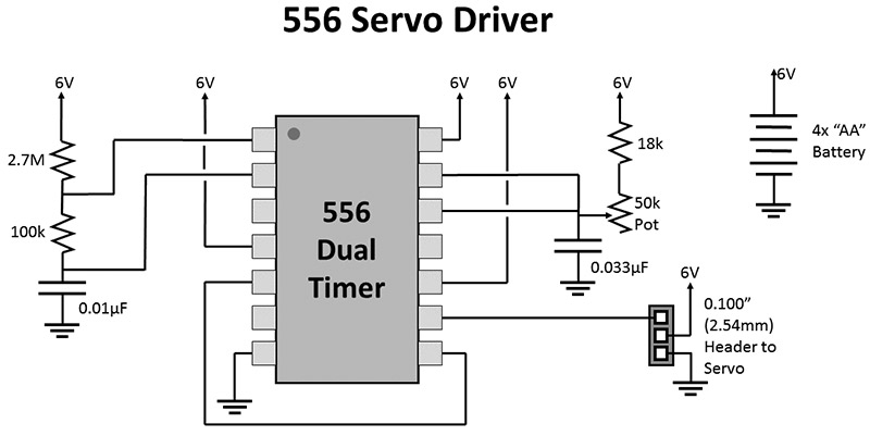
FIGURE 4. A 556-based servo generation circuit.
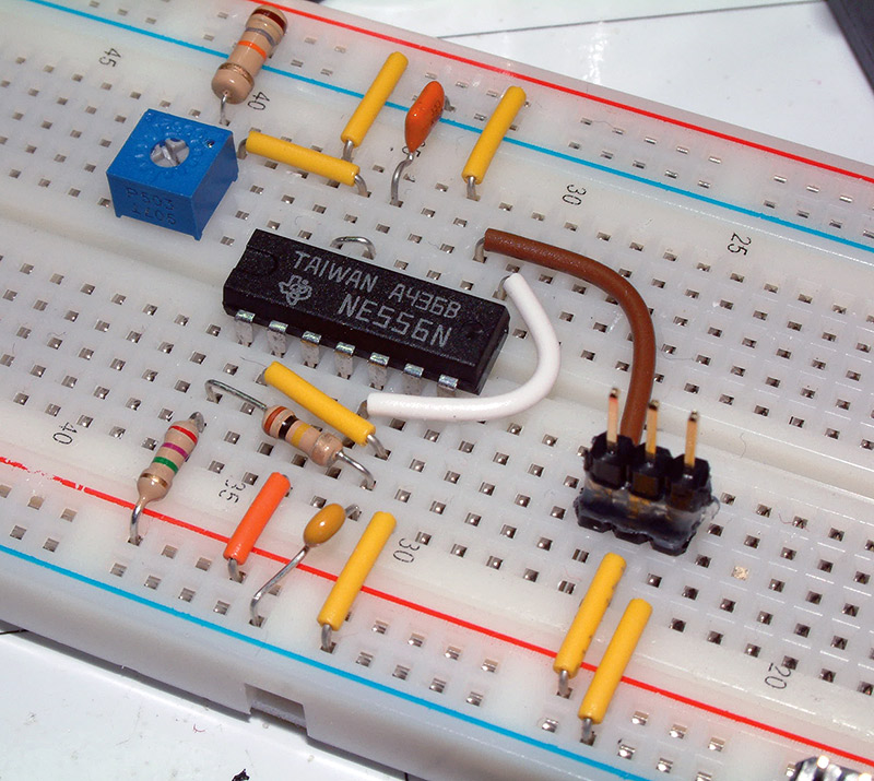
FIGURE 5. The 556 servo control circuit built on a breadboard.
The 556 chip consists of two 555 timers:
- They produce a pulse every 20 ms.
- They take the pulse from one as a trigger, and create a pulse that ranges from approximately 600 µs to 2,400 µs to control the servo’s position.
This circuit is something that people are always amazed at seeing — I highly recommend that you take a few minutes and make up a couple for yourself.
There are a number of single 555 circuits available for driving servos, but if you look at the output waveforms, you will see that the period changes with the width of the pulse output. While changing the pulse rate — as long as it’s not too drastic — shouldn’t be a problem, one of the things that I strive for is a constant pulse rate as it ensures proper operation of the servo.
When you’re building the 556 circuit (as well as the later circuits), you might notice that it’s a good idea to match the direction of rotation of the potentiometer with the direction of rotation of the servo. This makes it easier to see the motion of the servo — and that the speed of the servo (about 360 degrees/s) is not as fast as you can turn the potentiometer. The speed of the servos can be an issue when it comes to some applications.
Arduino Control
So, now that we know we can control a servo and that it works according to the specifications, let’s look at controlling it with a computer system. I’m going to use an Arduino for this, but for the information provided here, really any controller can be used.
I don’t think I have ever seen a servo that I would consider to be correctly connected to an Arduino except when a servo driver shield has been used. There are two reasons for this: The first is providing power to the servo, and the second is the control signal voltage level sent to the servo. Providing electrically safe power and control signals to the servos is actually quite easy to do, and doesn't significantly add to the cost or the complexity of the circuitry.
The first issue is providing power. I tend to cringe when I see an application that uses the power that comes from the Arduino’s +5V regulator as shown in Figure 6.
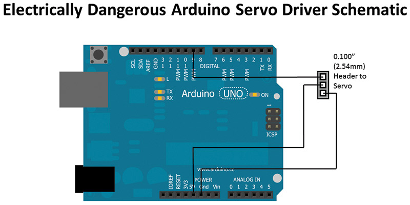
FIGURE 6. Servos powered by Arduino onboard regulator — danger!
If you look at the Arduino’s schematic, there is the NCP1117ST50 Low Drop Out (LDO) regulator that can source up to 1A of current but it is bypassed when the Arduino is plugged into a PC’s USB port (which is generally limited to 500 mA with a 500 mA fuse on the Arduino board).
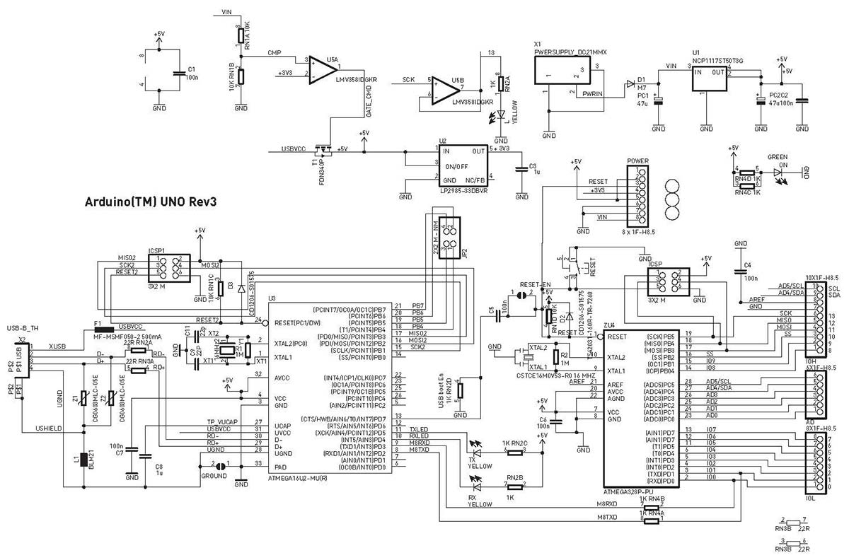
Arduino Uno Schematic
This means that drawing too much current could blow the fuse on the Arduino or draw too much current from the PC’s USB port, potentially damaging it.
You might think I’m exaggerating and worrying over nothing because you have looked at the current drain of the servo above and added them up:
200 mA current draw for ATmega
150 mA current for Servo 1
+150 mA current for Servo 2
500 mA Total
This means that the Arduino plus two servos should work with the 500 mA from the USB port; the 150 mA servo figure is based on the servo not moving and/or not stalled (unable to move to its commanded position). In these cases, I have measured current draw per stalled HS-422 servo to be as high as 450 mA which — with the load of the other servo and MCU — is enough to blow the fuse on the Arduino or potentially damage your PC.
The solution is to provide separate power for the servos and buffer the control signal coming from the controller (Arduino, in this case) as shown in Figure 7.
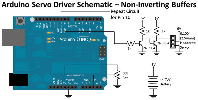
FIGURE 7. Proper Arduino servo connection with separate power supply and buffered servo control signals.
The buffering of the control signal may seem like overkill and, in some cases, may seem to be in error because certain datasheets specify the voltage level of the control signal going into the servo as being 3V to 5V. Unfortunately, this specification isn’t consistent (even for the same servos), and when I look at the input of servo controller chips (like the NJM2611), the inputs are not limited to any set value.
The buffering of the control signals prevents any current from the servo’s electronics being driven back into the controller, which saves power and protects the I/O pin. The two transistors and three resistors (which can be almost cut in half as shown below) should only cost $0.10 and eliminate any potential issues down the road.
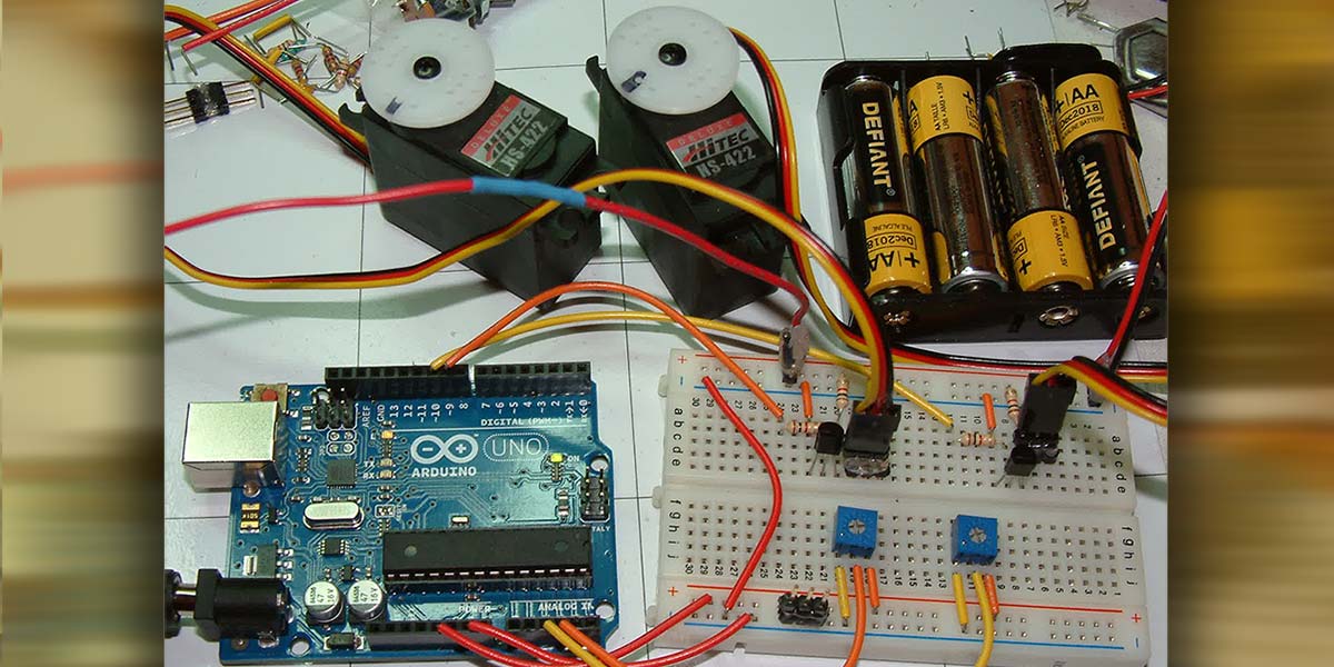
The circuit can be assembled onto a breadboard connected to an Arduino as shown in Figure 8.
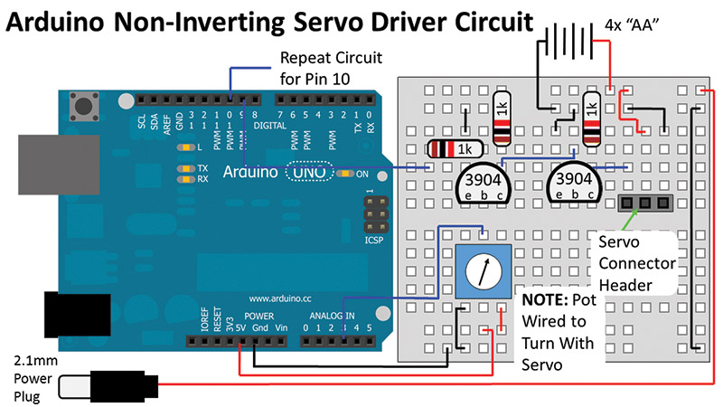
FIGURE 8. Breadboard wiring of Arduino with separate power supply and buffered servo control signals.
When I put the two together, I use the bottom red rail of the breadboard as the Arduino’s +5V; I refer to it as “Vref” and external (battery power, in this case) as “Vperif.” This circuit (with two potentiometers and two servo buffers) will be used for the example applications throughout the rest of this article.
The 2.1 mm power plug is used to power the Arduino from the four AA battery pack when the USB cable has been withdrawn. Note that there isn’t a ground connection (to avoid making a ground loop), and that the length of the wire should be at least 10” (25 cm) to reach comfortably from the breadboard to the Arduino. I use a big physical connector and cable instead of wire to the Arduino’s Vin pin so that it is visually obvious when it is plugged in and interferes with plugging in the USB cable.
Test Applications
Once you have built the circuit, you can test it with the Arduino application “Application_01_-_Basic_Servo_Signal” available in the downloads. This application will send a pulse to the servo connected to the Arduino’s pin 9 that is the intermediate position.
Regardless of how safety conscience I am, there are more than a few applications where the Arduino’s I/O pins provide power along with the control signal to a servo (like in Figure 9) in an effort to minimize the wiring needed for an application.
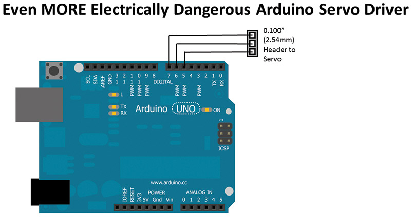
FIGURE 9. Now, this is just silly.
This is marginal for a servo like the HS-422, but actually works quite reasonably well for small low current servos in applications where they are unlikely to stall.
Regardless of how well it works, I still highly recommend using the separate power supply and buffering the input as discussed above. If you are curious, you can try “Application_02_-_Basic_Servo_Signals_for_Never_Do_Circuit” with this circuit. However, I recommend that the servo is only connected for a few seconds, and you do not try to move to the output wheel while it is connected (this is a stall condition which will draw more current).
Going back to the circuit in Figures 7 and 8, let’s experiment with the servos and how it works. If you load “Application_01_-_Basic_Servo_Signal” into the Arduino development environment and transfer it to the Arduino, try turning the output wheel of the servo. You will find it’s very stiff. This is due to the consistent series of pulses that keep the servo “active.”
If you were to measure the current being drawn by the servo, you should see around 150 mA while the servo is sitting with no load. If you attempt to turn the servo wheel, you will be met with fairly stiff resistance, and you will see the current draw increase considerably.
Application 1’s pseudo-code looks like:
Enable Servo IO Pin for Output
while (1 == 1) { // Loop forever
Send Pulse // Send Pulse every 20ms
// or so
Wait 19ms
}
Now, load in “Application_03_-_Single_Pulse_Out_Application” which only sends an initial pulse to set the servo position. If you measure the current, you’ll see that it has fallen off to just a few mA, and there is little resistance (lots of inertia, though) when you try and turn the output wheel. This is because the servo isn’t getting a constant stream of control pulses which is setting the desired position. Application 3’s pseudo-code looks like:
Enable Servo IO Pin for Output
Send Pulse // Send Pulse To Set
// Initial Position
while (1 == 1) { // Loop forever
}
Not having a constant stream or having an irregular stream will end up causing problems with the servo’s ability to set the desired position and stay there.
It’s very important to create the optimal control signals for the servo with absolutely minimal impact in the main line of the application. When I say minimal, I mean as little or no processor execution disruption to generate the servo control pulses.
You may be familiar with the Arduino “SoftwareServo” library which is used for “Application_04_-_One_Servo_SoftwareServo_Library_Example” and “Application_05_-_Two_Servos_SoftwareServo_Library_Example.” These applications read the potentiometer value(s) and pass them along to the servo(s).
The “SoftwareServo” library .zip file is available in the downloads and will have to be downloaded and installed as a “Contributed Library” in your Arduino development environment.
The “SoftwareServo” library provides the refresh method which outputs the position of all servo objects simultaneously, with the shorter ones first. It works quite well except for two issues.
The first issue is that this method will take at a minimum around 700 µs and at a maximum 2,500 µs each time it fully executes (more on this qualification later). With a 20 ms pulse stream, this means that 3.5% to 12.5% of the cycles executed by the Arduino are spent driving the servos.
To make matters worse, the servo pulse will only execute if at least 20 ms has elapsed. If you look at the code in Applications 4 and 5, you’ll see that there is a 15 ms delay before executing the refresh method. The time required to read the potentiometer ADC(s) takes much less than 15 ms. So, after a reading, the pulse is not sent out. Then, the code loops around again, takes the ADC readings, and then outputs the pulses — 30 ms or more instead of the 20 ms. This can be seen in the pseudo-code for the application:
while (1 ==1) { // Loop forever
Read ADC on Pin 3 and Set Left Servo with its
value
Read ADC on Pin 2 and Set Right Servo with its
value
Delay 15ms
Call the “refresh” method
If >= 20ms past since last pulse
Send pulse(s) to servos
}
This is the application timing impact that I noted above. It can make it quite difficult to get an application (especially a robot application where sensor data is used) to be properly timed.
As an aside, the SoftwareServo library brings up an interesting philosophical question which goes back to the analog versus digital nature of servos that was discussed previously: How many “steps” are there for a servo?
If you use SoftwareServo, you have 180 discrete degrees, but if you consider that the Arduino’s processor is running at 4,000,000 instructions per second in the 1,800 µs range of the servo pulse, there are 7,200 instruction cycles. Doesn’t this mean that there are 40 possible positions between each “degree” in the Arduino?
As I said, it’s a philosophical question, but an important one to think about as we discuss different methods of driving servos below.
With the “SoftwareServo” as a reference point, I want to be able to create servo control signals that:
- Do not have an impact on the operation of the application code.
- Provide a stable 20 ms pulse train.
The answer goes back to my first class in assembly language programming in University. If you are looking to provide a consistently timed event, use the processor’s built-in timer and interrupt.
The “TimerOne” Arduino library (available in the downloads) provides access to the ATmega Timer1 module and its built-in peripherals (including the PWM, which we will be taking advantage of in the next application). This library is used in “Application_06_-_One_Servo_Timer_Interrupt” and “Application_07_-_Two_Servos_Timer_Interrupt” uses a state machine to determine what are the I/O operations along with timing, and can be described using the pseudo-code:
Enable Servo IO Pin(s) for Output
Start Timer with “Timer1IRQ” Interrupt Handler
state = finalDelay;
while (1 == 1) { // Loop forever
Servo1value = left Pot
Servo2value = right Pot
Delay 10ms
}
Timer1IRQ { // Timer output state machine
switch (state)
case leftServoStart:
Servo1Pin High
setTimer = Servo1value
state = leftServoEnd
case leftServoEnd:
Servo1Pin Low
setTimer = 2,500us - Servo1value
state = rightServoStart
case rightServoStart:
Servo2Pin High
setTimer = Servo2value
state = rightServoEnd
case rightServoEnd:
Servo1Pin Low
setTimer = 2,500us - Servo1value
state = finalDelay
case finalDelay:
setTimer = 20,000us – (2,500us *
#servos)
state = leftServoStart
}
Notice that in this application, the mainline code is completely independent of the servo control signal generation. If we were to assume that every 20 ms, each Timer1IRQ instance took 50 instruction cycles (and there are five of them), and in 20 ms, there are 80,000 instruction cycles, the percentage of cycles lost to generating the servo control signals is 0.3125%. This is constant, however, and does not affect the operation of the mainline code. If we expand this to eight servo outputs (at which point there would be 16 states), this loss increases to a constant 1.0% — still a lot better than the 3.5% to 12.5% of the SoftwareServo library.
You may question why the application uses 2,500 µs for the length of time for the code for each servo when the maximum length of time that a pulse can be active is 2,400 µs. The reason is a practical one to eliminate the problems when the timer is loaded with 2,400 µs — that is, 2,400 µs or zero.
Depending on the MCU, the timer will immediately cause an interrupt which will have it jump to the next state immediately, or will wait for the timer to count through and overflow. Neither option is desirable, so while I could have gone with 2,401 µs, I decided to go with 2,500 µs which gives me a maximum of eight outputs over 20 ms, with each one spaced exactly 2,500 µs apart.
By using the timer and its interrupt, I can comfortably generate control signals for eight servos with only a 1% loss of machine cycles, as well as execute completely asynchronously so the mainline code (where sensor operations and high level execution takes place) has minimal disruption.
Would it surprise you if we could do better?
PWM
For those people who are very familiar with the Arduino, you probably had an idea why I picked pins 9 and 10; these are the PWM outputs for Timer1. The PWM generator in a microcontroller continually compares the current value of a timer to an expected value, and when the timer value is less than the expected value, it outputs a high value on an I/O pin.
When the timer value is greater than the expected value, then a low value is output on the I/O pin. The ATmega used in the Arduino has two PWM “channels” dedicated to Timer1 (other microcontrollers can have as many as eight PWM channels dedicated to a single timer, and have multiple timers with multiple PWM channels).
The PWM generation does not require any I/O cycles of the processor at all, so you could argue that the improvement over the other versions is infinite. How’s that for better?
“Application_08_-_One_Servo_PWM_Output” and “Application_09_-_Two_Servo_PWM_Output” implements the servo control over the two Timer1 channels. When they run, you should not see any difference compared to the timer interrupt versions of the servo control programs. However, they do not take up any processor cycles during execution. The pseudo-code for these applications is:
Enable Servo IO Pin(s) for Output
Start Timer with “Timer1IRQ” Interrupt
Handler
state = finalDelay;
while (1 == 1) { // Loop forever
Servo1PWMvalue = left Pot
Servo2PWMvalue = right Pot
Delay 10ms
}
All the execution time is devoted to reading the sensors and writing the new value to the PWM registers. It doesn’t get any simpler than this.
When you look at some servo datasheets, they will indicate that the “Control System” is “PWM.” This is something of a misnomer, as we’ve just demonstrated. It is possible to use a PWM signal to create a valid series of control pulses for a servo, but they should not be considered to be a PWM signal.
A PWM signal is used to directly control the power to a motor or to set an analog level, whereas the control signals here are used to set the position of the servo. This is splitting semantic hairs, but it’s important to think about exactly how the signals being produced are used.
There is a potential issue with using PWM to drive servos, and that is the number of bits available to the PWM’s timer. In the Arduino’s Timer1, there are 16 bits for a total count value of 65,536. However, the timer runs off the system clock divided by two (which is 8 MHz), which means that at full speed it takes 8.2 ms to run through the clock. So, to be able to support a 20 ms cycle time, the Timer1 input is passed into a “prescaler” which divides it by eight. That means the maximum time for Timer1 now to cycle through is 65.5 ms (or 1 µs for each timer click); for 20 ms, 15 of the 16 available bits are required (the high bit of Timer1 is never set when counting off 20 ms).
Of what’s left over, 600 µs requires 10 bits and 2,400 µs requires 12 bits, with a range between them of 1,800 bits. This gives us 10 values for each “degree” instead of the 40 which was possible using the processor.
I’ve done this analysis because the 16-bit counter in Timer1 does allow for (more than) adequate control of the servos, but what about the eight-bit counters of Timer0 and Timer2?
Going through the same analysis, we will discover that the PWM ranges are from six to 24, or 10 degrees per value — a 100 times loss of resolution. This makes it sound like an eight-bit timer with PWMs is impractical for creating servo control pulses.
I would say maybe, maybe not. If your application was to control a robot arm precisely for assembling a product, I would say this isn’t the right way to generate the signals. An eight-bit timer and PWM would be fine for controlling continuous rotation servos, though. I would think that an eight-bit timer and PWM would be adequate for controlling the leg of a spider bot; 18 positions for the leg servos seems very reasonable for just such an application.
Don’t dismiss anything until you’ve thought it through.
On that note, I want to go back to the two transistor non-inverting buffers that are used to isolate and voltage-shift the control signals from the Arduino to the servos. I originally used that circuit because I was using the SoftwareServo library, and the servo control signals produced by it are what I would call “positive” — the pulse produced by this software is in the same orientation as what’s required by the servo. So, what about the pulses produced by the TimerOne library code?
What happens if I invert the signals (as I did in “Application_10_-_Two_Servos_Inverted_Timer_Interrupt” and “Application_11_-_Two_Servos_Inverted_PWM_Output”) and then pass them through a single transistor inverting buffer like the one in Figure 10, wired as in Figure 11, and shown in Figure 12?
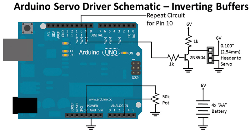
FIGURE 10. Arduino servo connection with separate power supply and inverting buffered servo control signals.
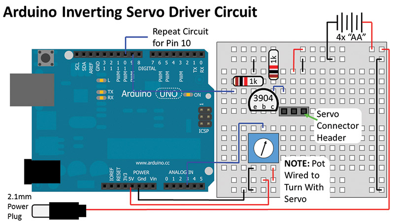
FIGURE 11. Breadboard wiring of Arduino servo connection with separate power supply and inverting buffered servo control signals.
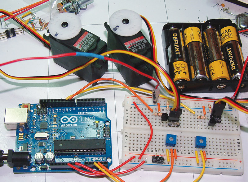
FIGURE 12. Servo control circuitry with separate power.
We get a slightly cheaper version of the circuit that works just as well. If you were to probe the signals going into the inverting buffers, however, you’d see the negative waveform of what was expected.
That’s just about everything there is to know about powering radio control servos and generating their control signals.
Recap
Just to recap ... electrically, I have given you some suggestions about powering servos in your application, as well as buffering the signals from the MCU to the servos to ensure there are no voltage difference issues. From the signal generation perspective, there are four different methods of generating servo control signals, ranging from ones that are quite intrusive in terms of the processor’s cycles, to one that is completely invisible to it. Hopefully, this has been an informative and useful rant and we’ve mastered how this decade's old technology works. SV
| 556 Servo Driver Bill of Materials | |
| 1 | 556 Dual Timer |
| 1 | 0.033 µF Capacitor |
| 1 | 0.01 µF Capacitor |
| 1 | 2.7M 1/4W Resistor |
| 1 | 100K 1/4W Resistor |
| 1 | 18K 1/4W Resistor |
| 1 | 50K Single Turn, PCB Mountable Potentiometer |
| 1 | Servo Header (see text) |
| 1 | 4 AA Battery Holder with Batteries |
| Misc. Breadboard/Prototying PCB with Wires | |
| Arduino Driver — Non-Inverting Buffers Bill of Materials | |
| 1 | Arduino Uno |
| 4 | 2N3904 NPN Transistors |
| 6 | 1K 1/4W Resistors |
| 2 | 50K Single Turn, PCB Mountable Potentiometers |
| 2 | Servo Header (see text) |
| 1 | 4 AA Battery Holder with Batteries |
| Misc. Breadboard with Wires | |
| Arduino Driver — Inverting Buffers Bill of Materials | |
| 1 | Arduino Uno |
| 2 | 2N3904 NPN Transistors |
| 4 | 1K 1/4W Resistors |
| 2 | 50K Single Turn, PCB Mountable Potentiometers |
| 2 | Servo Header (see text) |
| 1 | 4 AA Battery Holder with Batteries |
| Misc. Breadboard with Wires | |
Article Comments