Robotic Sensors
By John Blankenship, Samuel Mishal View In Digital Edition
Part 1: Identify and Distinguish
The aspiration of many robot hobbyists is to create a machine that uses autonomous behavior to achieve a goal. Unfortunately, many roboticists assume that such goals are limited to simple tasks like avoiding objects or following a line. This article discusses how giving your robot even a rudimentary ability to identify objects can increase its ability to cope with more complex situations.
A typical hobby-level robot might avoid objects while it randomly roams around a room. Nearly all hobbyists have observed such a behavior, and only a novice will be overly impressed by the capabilities of such a robot. In actuality, the robot’s random movement is the source of discontent. The robot’s only goal is the avoidance of anything that gets in its way. If the robot could identify important objects, then its ability to react to its environment could be greatly improved.
If, for example, the robot could identify both a soccer ball and a goal, then it could be programmed to find the ball and deliver it to that goal. The task of avoiding other objects during this endeavor then becomes a means to an end, rather than a goal of its own.
Programming a robot to actually play soccer can be very ambitious, but a simplified version of this activity can help demonstrate how even just a hobby robot can identify objects within its environment.
The Needed Sensors
In order to achieve this task, our robot will need to have several types of sensors. The details of the algorithm we develop will depend heavily on the actual sensors used. So, we will use a modular approach to make it easy to implement the principles discussed here with sensors you might already have.
First, our robot will need a ranging sensor capable of measuring the distance to objects. We’ll use an ultrasonic sensor mounted with a forward orientation. The purpose of this sensor will be to locate objects that are reasonably close to the robot.
The robot will also require a beacon detector to easily identify the location of a specified target (a beacon will be mounted above the soccer goal). We will use a RobotBASIC IR beacon, but you could use a flashing light or a uniquely colored object. (A beacon can be almost anything, as long as you have a sensor that can detect it.)
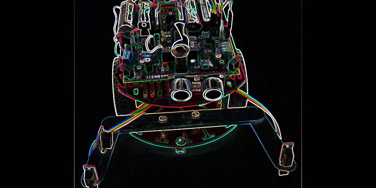
We’ll mount a U-shaped trap to the front of the robot as shown in Figure 1.
![]()
Figure 1.
This trap is made from craft sticks (like large Popsicle sticks) that make it easy for the robot to trap the ball and push it around.
The trap has three sensors of its own to help identify and maintain control of the ball. Our trap sensors are digital IR versions (Pololu #1134) with a fixed range of about four inches. Two are mounted on the tips of the trap — pointing forward — with the third mounted on the side pointing inward (refer again to Figure 1). We will see how these sensors are used shortly.
Figure 1 also shows a Parallax PING))) ranging sensor (part #28015) mounted on the very front of the robot, as well as a beacon detector which is a Vishay TSOP34156 with a short cardboard tube taped to the front of it to make it more directional.
Our robot is a Magician chassis (available from Zagros Robotics; an updated version is available here) controlled by the RobotBASIC Robot Operating System (RROS), along with a special printed circuit board (PCB) to make it easy to directly interface with all the sensors.
Once you understand the principles we’re using here, you can create a similar project with almost any hobby robot equipped with appropriate sensors.
Most sensors supported by the RROS plug directly into the PCB. As mentioned earlier, our soccer robot needs three sensors mounted on the ball trap. Figure 2 shows how easily this can be done.
![]()
Figure 2.
We simply drill the appropriate holes for the IR sensors, then hold them in place with the female end of the cables that connect the sensors to the line sensor inputs on the PCB.
Figure 3 shows the robot approaching the target goal where the ball is to be deposited.
![]()
Figure 3.
Notice the IR beacon mounted above and behind the goal. Complete information on how the RobotBASIC beacon system works can be found in the RROS manual which can be downloaded from www.RobotBASIC.com.
The ball we used has a nippled surface which prevents it from rolling away from the robot too quickly. This made development of the algorithm much easier. The soccer goal is made from foamboard panels; we often use this material to create walls and obstacles for our projects.
Implementing the Algorithm
We used RobotBASIC to implement the algorithm. Its easy-to-read syntax makes it simple to translate programs for use with other controllers. Figure 4 shows how quickly the algorithm can be implemented if it is assumed that all the details are handled by separate subroutines.
#include “RROScommands.bas”
#Include "InitializationRoutines.bas"
gosub InitRROScommands
gosub InitMagicianChassis
rCommand(SetSenseInvMask,7)
main:
gosub GetObject // acquire the ball
gosub MoveToBeacon // move it to the goal
end
Figure 4.
The first part of Figure 4 uses library routines to perform the initialization necessary for the RROS to control the Magician chassis and our chosen sensors. There is also a command to set an inverse mask. This is needed because we attached the trap sensors to the RROS line sensor inputs.
The line sensors report true when they see a black line (no reflection); we need to invert this logic with the trap sensors so they will report true when a reflection (from a ball or other object) is detected.
Inside the main program, the subroutine GetObject is used to find a ball. Once a ball is found, the subroutine MoveToBeacon will move the ball to the goal. Figure 5 shows how the ball is obtained. The outer repeat loop will continue looking until a ball is found.
GetObject:
repeat
rCommand(SetSpeed,25)
rCommand(SetTurnStyle,100)
// look for some object that is close by
repeat
found = 0
for i=1 to 100
rTurn -1
if rRange()<40
found=1
break
endif
next
if not found
// move around a little to help find an object
rTurn -20
if rRange()>20 then rForward 20
endif
until found
// some object now in view - move to it
found = 0
for i=1 to 100
rForward 1
if rSense()
found=1
break
endif
next
if found
// object found, now see if it might be a ball
found = 0
// try for a short time to get it in the hand
for i=1 to 50
if rSense()=1 // something is in the hand
found = 1
break
endif
if rSense()=6 // ignore big objects
rForward -40
rTurn -30
endif
while rSense()=2 // right trap sensor
rTurn 1
wend
while rSense()=4 // left trap sensor
rTurn -1
wend
rForward 1
next
endif
until found // something is now in the hand
return
Figure 5.
Inside the loop, the speed is set to 25% of maximum to better locate objects. Also, the turn style is set to 100 so that the robot will rotate around its center when turning.
An inner repeat loop uses a for loop to rotate the robot left for a short time as it looks for a nearby object. You may need to adjust the for loop and the range distance to work for your particular situation.
If an object is not found, the robot turns a little and moves forward. This serves as a random movement to help the robot roam around until it “sees” an object to examine.
When the inner repeat loop terminates, it indicates an object has been found and a for loop moves the robot forward (for a short time) to see if it can find the object detected by the ranging sensor. The object is assumed to be found if any of the trap sensors detect it.
Identifying the Ball
Once an object is found, the program tries to identify it. Another for loop lets the robot briefly try to get the object into the trap. If it fits inside the trap, we will assume it is a ball.
This is a very simplistic way to distinguish the ball from other objects, but it serves to demonstrate the principle. A more robust algorithm could use a color sensor or other alternative approaches to help ensure that the desired object was found.
While trying to get the ball into the trap, the robot will attempt to adjust for situations it might encounter. If both of the front trap sensors are triggered, a large object (such as a wall or the goal) will be assumed, and the robot will back away and continue looking for the ball. If either of the front trap se
sors are triggered, the robot will turn left or right to try to center the object so it can fit into the trap as the robot moves forward.
There's an important aspect to this routine. The robot always uses for loops to limit the amount of time it tries to perform any given task. If the task being performed is not accomplished in a timely manner, the robot restarts the entire routine. While this may prevent the robot from occasionally obtaining a ball it has found, it also prevents the robot from getting stuck in a loop where the robot’s actions make no sense at all.
Moving to the Goal
Once the ball is in the trap, the subroutine in Figure 6 will find a beacon and move the robot toward it so that the ball can be deposited at the goal.
MoveToBeacon:
// first face the beacon
rCommand(SetSpeed,40)
rCommand(SetTurnStyle,0)
while not rBeacon(0)
rTurn -1 // rotate to left
wend
// then move to it
rTurn 10
rCommand(SetTurnStyle,0)
while (rSense()&1) and not(rSense()&6)
rForward 1
if rBeacon(0)
rTurn 1
else
rTurn -1
endif
wend
return
Figure 6.
At the beginning of this routine, the speed is increased slightly to help the robot keep the ball in the trap as it turns to look for the beacon. The turn style is also changed to zero, which simply causes the robot to rotate around one wheel rather than around its center.
This motion helps keep the ball in the trap. The robot will turn left in this manner as it looks for the beacon located at the goal.
When the beacon is found, the robot turns back to the right slightly to ensure that it is aimed at the beacon or a little to the right of it. It then moves forward, turning to the left when the beacon is not seen, and to the right when it is. This action effectively lets the robot follow the beacon’s signal. It does so until one or more of the front trap sensors indicate that the goal has been reached.
Conclusion
We have provided an easy-to-understand example of how a robot can locate and identify a ball within its environment, and then move it to a goal. A more robust algorithm for obtaining the ball could certainly be implemented — especially if additional sensors are utilized.
The hardware requirements for this project are minimal, so you might find you can experiment with these principles using a different robot. Watching the robot seek out the ball, maneuver to trap it, and move it to the goal is definitely worth the effort.
![]()
Figure 7.
Next time, we'll build on the ideas discussed here and show how a robot (see Figure 7) can find small objects, then retrieve them with an easy-to-build arm. SV
Article Comments