The Basics of Soldering — Part 3
By Bob Wettermann, Nick Brucks View In Digital Edition
Surface-Mount Technology (SMT) parts are by far more common than the through-hole component mounting style for today’s printed circuit boards (PCBs). Open up any electrical device around your house (ideally one you don't care about too much) and you'll notice almost every component lies flat on the board rather than having a lead run through the PCB. This style of PCB mounting allows SMT style components to be placed very quickly on to PCBs, while taking up much less space than their through-hole counterparts. This makes them very desirable for modern electronics.
Typically, SMTs are harder to hand solder than through-hole parts. Because of this, most industrial SMT soldering is done by machines. However, knowing how to solder SMTs by hand is a valuable skill if your project has strict space requirements or in the case where you need to rework or repair a machine-made project manually.
Before we get started, here’s what you will need for this installment:
- Soldering Iron with Small Chisel Tip
- Wire Solder
- Solder Flux
- Isopropyl Alcohol and Tissues
- Acid Brush
- Solder Wick
- Printed Circuit Board
- Tweezers
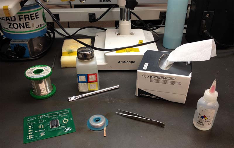
Figure 1. What you'll need.
As described in previous parts, remember to take the necessary ESD and safety precautions to avoid any potential hazards to you or to the components. Always assume the soldering iron tip is hot, and make sure to wash your hands after soldering — especially if you’re using tin-lead solder. It's also always a good idea to make sure that you are properly grounded (see Part I of this series) to avoid any ESD damage.
The first type of SMT we’re going to talk about are passive component packages as are typical of resistors and capacitors. These are usually flat rectangular chips with metallization typically covering five sides of the rectangular end, which will be soldered.
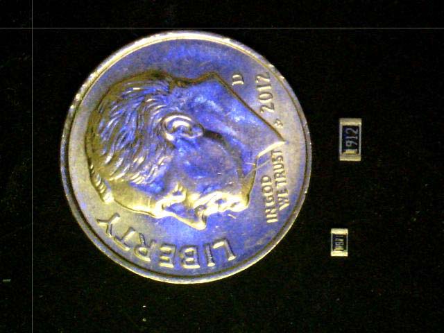
Figure 2. Two SMT resistors (dime is for scale).
The main challenge in soldering these component body style pieces in place is the same thing that makes them so useful in designing electronics: they’re small! Soldering these surface-mount components in place requires a steady hand and for you to take care with the amount of heat applied.
The big thing you have to watch out for is if the part “tombstones.” Since flat chips usually are very light, as the liquid solder cools and contracts the part can flip up to one side. The final result is called a “tombstone” because the part will stick up vertically. Hold down the center of the SMT with tweezers when soldering to prevent this from happening. Let’s get started.
- As always, clean the lands for soldering using isopropyl alcohol and wipe them dry with a kimwipe to ensure solderability.
- Melt a small drop of solder onto the tip of your soldering iron. Use this to tack a little bit of solder to one of the leads on the PCB.
- Once this solder has cooled, set the part down so that both leads are making contact with the pads. Apply liquid flux to one side of the part before soldering. At this point, make sure the part is properly aligned. After you solder down one side, the part cannot be moved without having to start over again.
- Reflow the side that you applied solder to earlier. While holding down the center of the part with tweezers, place the soldering iron tip on the junction between the pad and lead to reflow the solder. Refer to Figure 3.
- Apply flux to the other side. Place your solder wire on the point where the part meets the lead and use the soldering iron to apply heat. The small size of these parts means it will only take a little solder to do the trick. Be careful about holding heat on one side of the chip for too long; these components will conduct the heat from one side to the other easily, and begin to reflow the solder on the opposite side from where you’re applying heat. This will tombstone the part.
- Clean and inspect the final result. While this is not a comprehensive list, some common errors for soldering this style of component include:
- Component has nick or chip out that exposes the active elements.
- Component is not in contact with one pad surface (tombstoned).
- Component side overhang is more than 50% of the pad or width, or component end overhang of any amount.
- Solder fillets come in contact with the top of the component body.
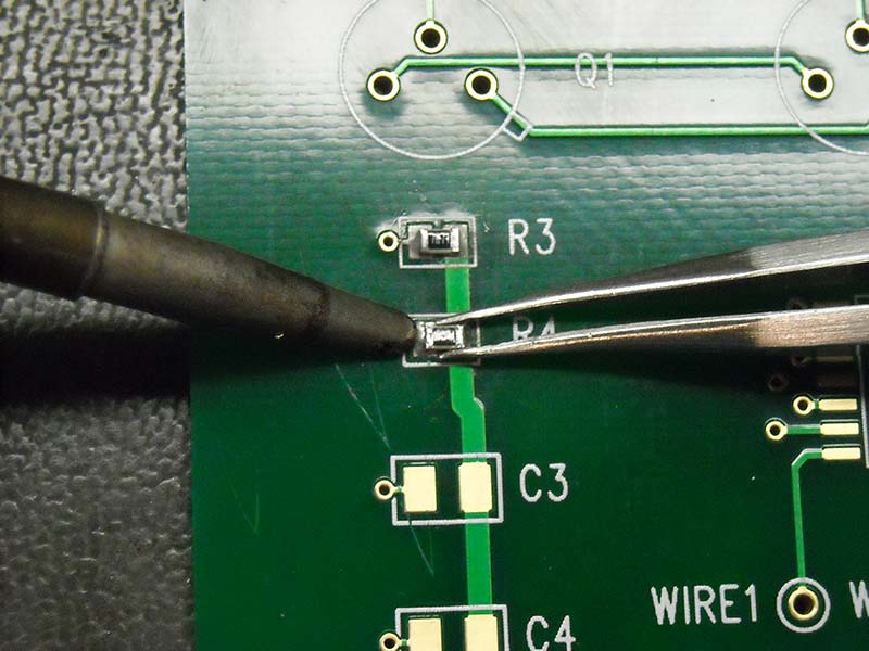
Figure 3. Soldering one side of a five-sided rectangular body SMT component.
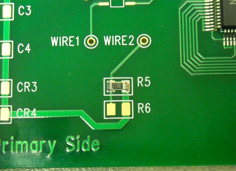
Figure 4. A fully soldered SMT resistor.
Another SMT type you’re likely to see are transistors and diodes. These generally look like a small component with three (sometimes more) flat leads coming out from the component body: two on one side, and one on the other. It is important to remember that these parts have polarity and the arrangement of the leads helps to identify that. This is useful, since running current through these parts the wrong way will damage them.
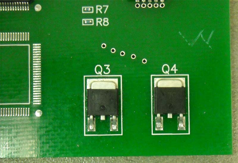
Figure 5. Two SOT components.
While you don’t have to worry about tombstoning like you do with flat chips, be careful about accidentally bending the leads of these parts. Bent leads tend to break and are a hassle to deal with when trying to solder down a part.
The process for soldering these components in place is:
- Clean the lands of the PCB with alcohol as before.
- Tin the pads (described in Part 2) by flowing solder onto the pads and then removing it with a solder wick. Remove any excess residue by cleaning with isopropyl alcohol and an acid brush.
- Set the part on the pads. Since there is only one way that the part will fit on the pads, you won’t need to line up any notches to ensure that you have the correct polarity.
- Apply flux to one of the leads of the part and solder-tack it down to hold the part in place. To tack the part down, place the soldering iron on top of the flat part of the lead and apply solder to the back of the curved side of the lead where it meets the pad.
- Flux and solder the other two leads, using the same technique of laying the soldering iron on top of the lead and applying solder to the back. Then, go back and solder the tacked-down lead.
- As always, clean and inspect the final product. Some errors you might want to look out for include:
- Component leads are more than 50% off of the pad surfaces.
- Component lead’s toe overhang.
- Excessive solder use.
- No evidence of properly wetted fillet around the lead and the pad surface.
- Solder fracture between the lead and solder fillet.
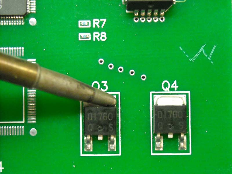
Figure 6. Tacking down one of the leads.
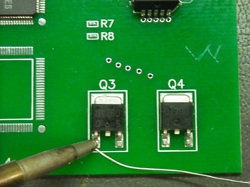
Figure 7. Soldering one of the leads.
The final type of components we’re going to look at are SOICs and QFPs. Even compared to the DIPs discussed in the through-hole soldering sequence (see Part 2 of the series), these parts have many leads. Because of this, they are both hard to solder and easy to damage. To avoid bent or broken leads, handle these parts gently.
- As always, clean the lands and pads with the alcohol method.
- Optionally, you can tin the lands to prepare for soldering.
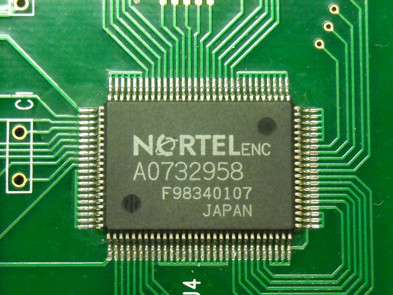
Figure 8. A QFP-100; note the large number of leads.
Before we continue, there are two ways that you can approach this task. You can apply liquid flux and solder to every pin one by one, which is an easier but tedious task. Alternatively, you can use a method called “drag soldering.” Drag soldering uses solder’s property of sticking to the pads to your advantage, but is more difficult to master.
To drag solder, apply a small bead of solder to the tip of your soldering iron. Then, at an angle of about 30 degrees on the foot of the lead, pull the soldering iron down the row of pads at a moderate pace. Don’t apply too much pressure as you go or you will bend the leads. On the last lead, sweep the iron away from the toe of the lead.
If you decide not to use drag soldering, soldering these parts lead by lead is similar to how you solder diodes and transistors — just on a smaller scale. Apply flux, and then while heating the top of the lead, melt a little solder onto the back.
- Whichever method you choose, place the part making sure you have the correct polarity as indicated by the notch on the chip.
- Once you’re satisfied that the part is in the correct place, tack down two diagonally opposite leads to hold the part down. Lay the tip of the soldering iron on one of the leads and apply a little solder at the junction where the lead meets the lands to tack it down.
- Drag solder or solder the pins one by one, depending on which method you chose earlier. Start with a side that doesn’t have a tacked lead to make sure the chip stays in place. Again, do not push too hard when doing this or the leads will bend.
- Inspect the connection, and reflow or add solder as needed (make sure to reapply flux every time you do so). Remove any solder bridges between leads by reflowing the solder where you see this occurring.
- Repeat this process for every side of the component.
- Clean and inspect the final product. Several common errors here include:
- Incorrect orientation.
- Component is positioned whereas leads are more than 50% off of the pad surfaces.
- Pad delaminated around the outside edge.
- PCB overheated damage (blistering/ delamination).
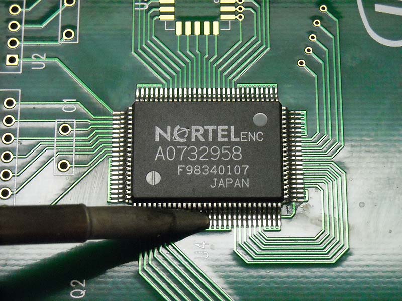
Figure 9. Drag soldering a QFP-100.
While we didn’t have time to go over every type of SMT available, these procedures are applicable to other body styles beyond just the three discussed. Drag soldering in particular is a useful technique to master if you find yourself hand soldering a lot of many-leaded components, since running through 100-pin chips lead by lead can be quite tedious. Even if you don’t solder SMT parts on a regular basis, it is still always good to have at least some knowledge of how to solder them — just in case.
In the final part of this tutorial, we will discuss the placement and soldering in place of advanced package types such as QFNs (leadless devices) and BGAs (area array devices). SV
Article Comments