Servo Magazine ( April 2015 )
Automation with Actobotics
By Jürgen G. Schmidt View In Digital Edition
As robot enthusiasts, we enjoy building fighting robots, line followers, and machines that can terrorize the local cat or dog. What we really want, however, is a robot that will clean our house, fold clothes, pull weeds, and perform all those jobs we'd rather avoid. So, if we can sometimes make some mundane task easier through robotics, I consider that a significant "win."
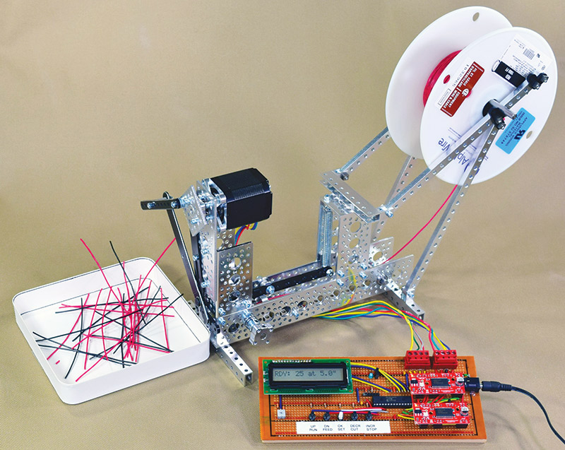
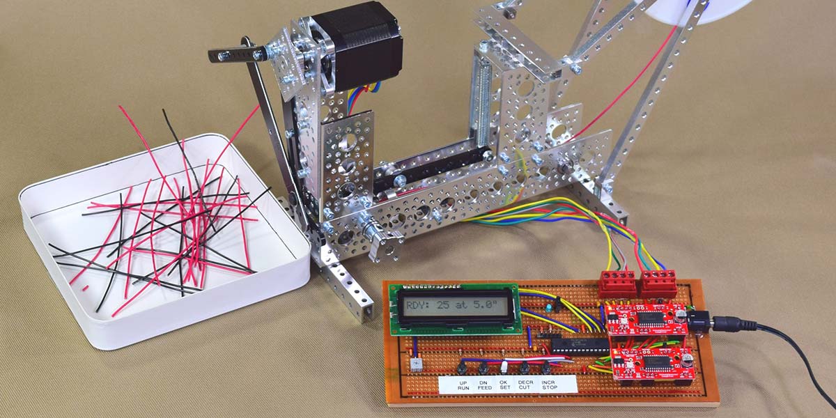
FIGURE 1. Finished Actobotics-based wire measuring and cutting machine with controller.
Background
Every serious “maker” has created some of the tools he or she uses. Sometimes it’s as simple as grinding a screwdriver to fit a particular screw, or as complex as building a custom CNC router for cutting out robot body parts. In the course of building gadgets in small production runs for myself and my customers, I run into simple, repetitive tasks and say, “I could train a monkey to do this,” but go on performing them because housing and training monkeys can be a messy business. Then, just before my mind goes absolutely numb from boredom, inspiration hits: “I could have a machine do this for me!” While my “monkey” hands are going on with their simple task, my brain’s engineering department kicks in, and my thoughts are off designing my next project.
In this particular case, the task is to measure and cut battery lead wires. I’ve done thousands of them over the years — all the same length. I didn’t want to spend a lot of time designing and building a machine to do this because the goal was to save time, not go off on a new development project. Also, I had orders to fill. Once the mental gears finished spinning, I pulled out my mechanical prototyping kit (a.k.a., Erector set) and got to work.
Growing up, I had many construction toys. I started out with wooden blocks, moved on to TinkerToys® and LEGOs®, and ultimately Märklin Erector sets. The Märklin kits had gears, wheels, shafts, beams, and other parts that allowed my creativity full reign. I used them into my teens, but then moved on to other things.
When I became interested in robotics some decades later, I tried to find my old Erector set but, unfortunately, it was lost during various moves. The German company doesn’t make the sets anymore but similar parts are available from the British (now French) company, Meccano. I accumulated a good collection of parts via eBay and built an assortment of robots — only some of which were deemed noteworthy by my cats.
When it came time to build my wire measuring machine, this was naturally the resource I turned to. The end result is shown in Figure 2 and you can see a YouTube video of it in action at http://youtu.be/ykguK0ylfCM.
FIGURE 2. Original Meccano-based wire measuring machine from 2003.
I couldn’t remember when I first built it — I had to track down the source code for the processor that drives it — and discovered I’ve been using it since 2003. The basic principle of the machine is a microprocessor-driven stepper motor connected to a rubber wheel via some gears. An idler wheel holds the wire against the rubber wheel, and every time I hit a button the stepper motor turns a fixed number of steps, resulting in uniform wire lengths that I then clip off.
This system has worked well enough, but every time I used it I thought of possible improvements. I kept putting them off because they weren’t really that important, and I was always in the middle of something else when I used it. Then, I got a project that would benefit from a more flexible machine. The drawbacks of the current one are:
- It doesn’t cut the wire.
- There’s no integrated reel holder.
- It doesn’t count the number of wires measured.
- I need to reprogram the processor if I want to change the length it measures out.
My upcoming project needed various lengths of lead wires, so it was finally time for an upgrade. The first question that comes to mind when considering an upgrade is, “Do I try to fix the original or do I start over?”
Selecting a Construction Kit
Making robot prototypes using the Meccano components, I discovered some of their limitations. The biggest one is that the structural members are made from soft steel. They’re heavy and bend easily. Other issues include the odd 4.08 mm axle and bore size, a lack of standard motor mounts, and no option for using ball bearings. While I could probably upgrade my hardware with the Meccano components, I have other projects in mind where I know the Meccano won’t work. I decided to start over since this project would be a nice way to get some experience with a new construction system.
In the course of reading Nuts & Volts and SERVO Magazine, I learned there were several robot construction systems available. In order to choose the best one for me, I came up with several guidelines:
- The components have to be strong but light enough to build real world machines, not just demonstrations.
- The building system needs to be friendly to “foreign” parts, so I can use motors and gears from other manufacturers.
- I need to be able to buy individual parts as opposed to preselected (and often expensive) kits.
- I would be building my own electronics, so the vendor offerings in this area would not factor into the decision.
Naturally, I started by looking at all the advertisements in SERVO Magazine. Then, I did some Internet searching. I found a number of vendors and kits, any one of which would have thrilled me as a Christmas or birthday present in my youth. Only one of the vendors had what appeared to meet my requirements: Actobotics from ServoCity. They have a wide range of parts and the online catalog shows many pictures of them in use, so I can order as many or as few of each as I want. I ordered a sampling of structural members, motor mounts, shafts, bearings, gears, and a hardware kit.
Upon examining them when they arrived, I found that the aluminum structural members are quite strong and light. The assembly hardware is based on hex socket head 6-32 screws. The balance of through and threaded holes in the various parts is such that you rarely have to use a nut to fasten things. If you’ve ever worked with an Erector set, you know that frequently you have to go to great lengths to fit a nut on a screw that comes out in some awkward location.
I put some pieces together in various combinations to get a feel for the components, and to figure out what I would need for my new machine. I did run into a little trouble with the plastic gears, which appeared to fit too tightly. Some SDP-SI gears of similar specifications worked fine, so I knew it wasn’t an issue with my design. I documented and reported this to ServoCity and got replacement gears in a few days. (Thanks, Brian!)
Apparently, the original gears I got had not been cut correctly. Turns out, I didn’t need the gears after all, but I’m sure they’ll come in handy in the future. Figure 3 shows my new parts organized into some plastic boxes.
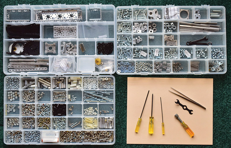
FIGURE 3. Actobotics parts, additional hardware, and tools.
The two trays at the top show what’s left over from the Actobotics parts after I built the new wire cutter. The tray on the bottom left is an over-the-years accumulation of 6-32 hardware, and on the bottom right I show some of my tools.
After playing — excuse me, working — with the Actobotics parts for a while, I brought out some other parts. I have some 1/4” bore pulleys from SDP-SI, as well as gears, salvaged stepper motors, Buehler gear motors, and, of course, the Meccano parts. As I searched for possible parts to combine with the Actobotics, I also discovered some sliding door wheels and bearings that had a 1/4” bore. The 1/4” parts fit nicely onto the Actobotics shafts. Actobotics supports several shaft diameters, but the most common is 1/4” (which is quite sturdy in contrast to the Meccano 4+ mm shafts).
While comparing some of the Meccano parts to the Actobotics ones, I made some exciting discoveries: there are several holes in the large channel that accommodate the Meccano shafts; some of the channel hole spacing matches the Meccano hole spacing; and the Meccano wrenches fit the Actobotics square nuts. Future Actobotics constructions may be able to adopt some of the now (for all practical purposes) orphaned Meccano pieces.
The New Design
Having decided that I made the right choice in selecting the Actobotics parts for my new machine, I started laying out a design. The core mechanism is the wire feeder. When I prepared my second order for parts from ServoCity, I also ordered some rubber feed wheels from SDP-SI, and some new stepper motors. I took a guess at the torque and probably ended up with too much power, but who can complain about too much power, right?
Figure 4 shows the basic path of the wire through the machine.
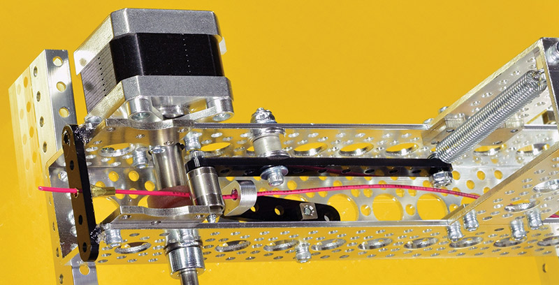
FIGURE 4. Close-up of wire feed path.
At the right side, you see the spring attached to the black tensioner arm. The silver cylinder that I use as an idler on the left end of the tensioner arm is a salvaged disk drive ball bearing whose bore was just the right size to slip onto the 6-32 screw. The wire is fed from right to left through various guides to the feed wheel, which is connected directly to a 40 oz-in NEMA-17 stepper motor via a 5 mm to 1/4” shaft adapter. The wire is pushed into a piece of brass tube, mounted so it’s positioned in the jaws of the cutter. The brass tube and the plastic cross member are held in place with one of my favorite adhesives: Amazing Goop (see sidebar).
Figure 5 shows the cutter assembly mounted on the feeder channel, as well as a mount for the wire reel.
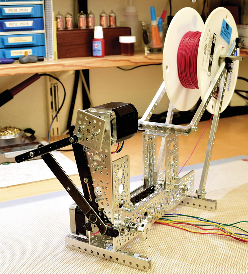
FIGURE 5. Completed Actobotics assembly.
For the cutter, I selected a simple wire stripper and removed the plastic handles and setscrew. Initially, I planned to use a small diagonal cutter to clip the wire, but I couldn’t find any that could be mounted conveniently. Then, I tried using scissors. The Fiskars I used have some available mounting holes after removing the plastic handles. However, the wire wouldn’t hold still; it kept wriggling away from the closing jaws.
Finally, I came upon an old wire stripper with the two notched cutting edges. These would trap the wire, and if I removed the wire gauge adjusting bolt, the wire stripper would become a wire cutter. Voilà!
I ordered a new one, drilled the necessary holes with carbide-tipped drill bits through the heat-treated steel, and -mounted it as shown. This is topped off with a 76 oz-in NEMA-17 stepper motor to power the cutting mechanism. The video listed in Resources demonstrates the linkage between the motor and the cutter.
From the upgrade wish list, I’ve addressed two items: a wire cutter and reel holder have been added. The other two items — counting wires and easily changing the length measured — would have to be handled by the controller.
Electronics
My skills and collections of spare parts have grown a bit since I made the original controller for the Meccano-based wire measuring machine. It consisted of a Microchip PIC16F84A connected to a DS2003 Darlington driver which, in turn, powered the four coils of the unipolar stepper motor I salvaged from an old IBM PC floppy disk drive. This is powered by an IBM PC power supply (visible in Figure 2) which provided the five volts for the processor and the 12 volts for the stepper motor. The only user interface is the pushbutton, which triggers a specified number of steps in the motor and then stops.
To achieve my design goals, the new controller would need a display and several buttons to change the operating parameters. I would also need to control two bipolar stepper motors. Since the activation sequence of the coils is a little more complicated in bipolar vs. unipolar steppers, I would be using dedicated controllers. Finally, I would need a microprocessor to manage all this.
The final lineup of major components consists of:
- Generic HD44780-based one-line/16-character LCD display
- Two EasyDriver 4.4 bipolar stepper controllers
- PIC18F26K22 processor
- Assorted pushbuttons, terminals, and other electronic components
- Solderable prototype board
- Regulated 12V 2A wall adapter
The schematic is shown in Figure 6, and the resulting assembly is shown in Figure 7.
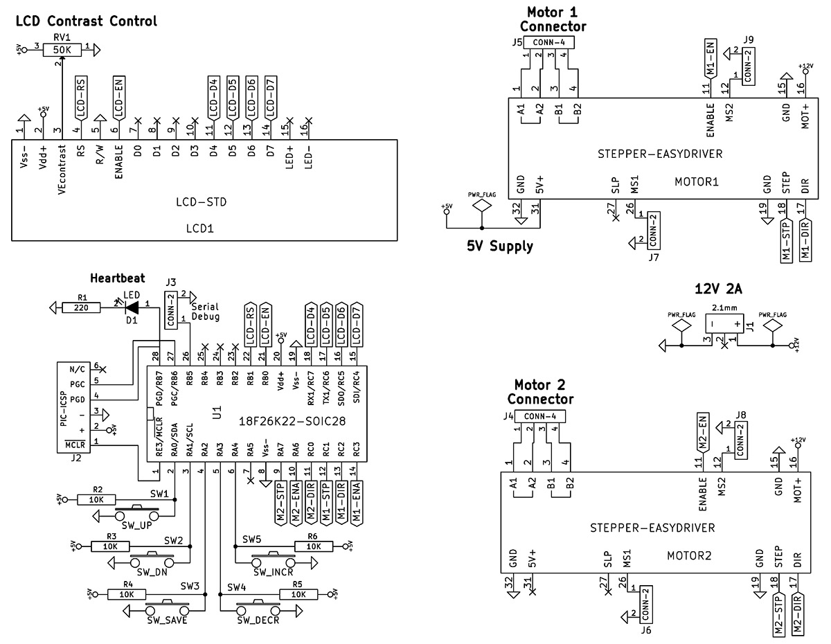
FIGURE 6. Schematic for controller.
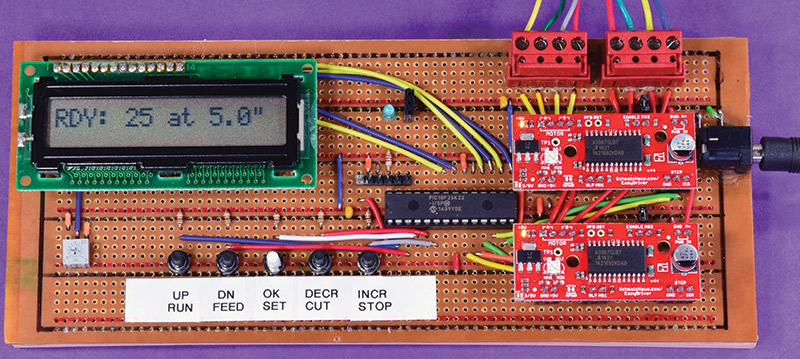
FIGURE 7. Finished control board.
There is no particular magic or rocket science in this control board. Connecting an LCD display to a controller has been described in other Nuts & Volts and SERVO articles, and there is a lot of additional information on the Internet.
The EasyDriver boards are a pleasure to use because they take all the mystery out of using stepper motors. You connect a power supply, connect the motor windings to the correct terminals, and then connect three signals to your processor. These signals are: Enable, Step, and Direction. Additionally, the EasyDriver boards have a step-down regulator, so you can use a single power supply for both motors and control electronics. There is an option to set this to either 5V or 3.3V, depending on the type of controller you’re using.
I selected the default 5V since I need that to drive the LCD. I selected the PIC18F26K22 because that’s what I’ve been using lately. I don’t take advantage of any of the special features or peripherals.
Due to the popularity of do-it-yourself 3D printers, CNC routers and engravers, egg printers, and other motion-control projects, there are several stepper motor control boards available from Pololu, SparkFun, and other suppliers. I selected the EasyDriver because it featured the step-down regulator, supported micro-stepping, and was in stock at a vendor where I was buying some other parts.
Micro-stepping is a nice feature that can give you very precise control of a stepper motor. Most stepper motors have 200 steps per revolution, or a resolution of 1.8 degrees per step. By setting the micro-stepping jumpers on the controller you can half, quarter, or eighth step for each step signal delivered to the controller, resulting in a possible resolution of 1,600 steps per revolution, or .225 degrees per step. Some controllers even allow 16th steps.
When selecting micro-stepping, you need to adjust the timing between steps to get maximum power and smoothness. I’ve used micro-stepping in other projects, however, I stayed with the regular full step for this one since that provided enough precision for my machine.
Software
Circuit design and software testing was done on a solderless prototype board to be sure I had the right connections, and to test some basic software routines. The initial software tests consisted of sending a sequence of STEP signals to the EasyDriver. Each stepper motor has its own preferred timing for optimum operation, so I needed to experiment. If you send the STEP signals too fast, the motor can’t keep up and stalls. Send them too slowly, and the motion is not very smooth. If you look at the code, you’ll see each motor has different timing to get a smooth motion. I ultimately ended up with two subroutines for driving the motors: Cut() and Feed().
Cut() simply makes a complete revolution of the motor by issuing 200 step commands. I’ve included the code for this subroutine below so you can see how easy it is to control a stepper motor with the EasyDriver:
void Cut( void )<br />
{<br />
 output_low( M2ENA );     // energize stepper<br />
 output_low( M2DIR );     // set direction of<br />
                // rotation<br />
 for( i=0; i<200; i++ ) {<br />
     // one full revolution at full step
   output_high( M2STP );     // send step pulse<br />
   delay_us( 1 );           // length of step<br />
                // pulse<br />
   output_low( M2STP );      // end of step pulse<br />
   delay_us( 1500 );        // allow time for<br />
                // motor to move<br />
 }<br />
 output_high( M2ENA );  <br />
     // de-energize motor since we don’t need<br />
     //  to actively hold the position.<br />
}
Feed() consists of three parts. There is a speedup, run, and slowdown. The purpose behind this is to avoid jerking on the wire spool too much. When you examine the code, you’ll see that for the speedup portions the initial time between steps is 1,625 microseconds (µs); this narrows to the ideal 1,200 µs in a loop. This speedup consumes one inch of wire.
The corresponding slowdown works in reverse and also consumes one inch of wire. The run section accepts a parameter — the value of which is the number of 5ths of an inch (0.2”) to feed. If the run parameter is set to zero, the minimum length of wire that can be cut is two inches.
A third subroutine is Settings() which sets up the operating parameters. Five pushbuttons are used in conjunction with the LCD to display, change, and save various parameters.
I’ve used this arrangement on many other projects, and it can be used for complex menus with several levels and many items. For this project, we have only two settings: quantity and length.
During menu operations, the five buttons are labeled: Up, Down, Decrease, Increase, and OK/Save. Up/Down is used to scroll through menu items; Decrease/Increase is used to change their value. The buttons are usually arranged in a cross pattern with the Save button in the center. I didn’t have room for that on my board, so they’re stretched out in a line. The OK/Set button is used to enter and exit the menu.
When not in menu mode, the buttons have dedicated functions. They are: Run, which feeds and cuts the number of wires set up in the menu; Feed, which feeds a single length; Cut, which performs a single cut; and Stop, which interrupts the program started by pressing Run. Please see the source code available at the article link for complete details and comments. This program was written for the CCS PIC C compiler, however, it should be easy to convert to other flavors of C and BASIC.
Operation and Conclusion
The controller displays the saved settings when it turns on as you can see in Figure 7, which shows that it is ready to cut 25 pieces of wire, each five inches long. Pressing the RUN button will start this process. Figure 1 shows the completed machine, and you can see it in operation below.
While testing and recording, I found it so entertaining — and even mesmerizing — that I quickly accumulated a year’s supply of cut lead wires. Now, I face the dreary task of stripping insulation from each end of the wires. While I have my monkeys doing that, I’ll be trying to figure out how to add that function to this machine.
This project accomplished two things: I now have a brand new, fully featured wire measuring and cutting machine, and I found a new construction set. I’m very pleased with the strength and overall utility of the Actobotics components.
The only non-Actobotics parts in the new machine are the rubber feed roller, a spring, the bearing idler wheel, and the wire cutter. While the two motors are not Actobotics parts, the construction system does provide mountings for the stock NEMA-sized stepper motors.
Based on my experience with this project and the desire to eliminate other boring tasks, I’ve already started planning my next Actobotics-based practical gadget. SV
A Practical Adhesive
When I glue something, I usually want it to stay put — until I want to make a change. Then, I'm stuck. That's the advantage of Erector sets: You have nuts and bolts and can assemble, disassemble, and reassemble at will. With glue, your decisions are usually final.

Several years ago, I discovered Household Goop, which has become my primary workshop adhesive. The glue — now called Amazing Goop — is an air-drying clear compound that dries to a tough rubbery consistency. Since it is air-drying, you can't glue two non-porous materials together face to face. You can, however, apply a filet around objects that need to be attached to each other.
The glue will stick to almost any clean surface. It doesn't work well on soft or oily plastics such as ABS and polyethylene. It does adhere well to acrylic and other hard plastics. Due to its flexibility, it's good for gluing fabrics and leather.
One of the key advantages of this adhesive for me is that it is removable. Its rubbery nature when dry is such that it holds together and can be stretched. This lets me pull it out of a seam or filet I laid down a week or a year ago.
Resources
Actobotics Hardware: www.servocity.com
76 and 40 oz-in NEMA 17 Stepper Motors: eBay
Rubber Drive Wheel: www.sdp-si.com Part #A 7T 5-UR07525
EasyDriver 4.4: www.allelectronics.com Part #SMD-67
Info: www.schmalzhaus.com/EasyDriver
Wire Stripper/Cutter: www.mouser.com Part #578-100X
Generic HD44780 LCD: Junk box
Other Electronic Components: Parts on hand
Amazing Goop: eclecticproducts.com
CCS PIC C Compiler: www.ccsinfo.com
Meccano Wire Measuring Video: http://youtu.be/ykguK0ylfCM
Actobotics Wire Cutting Video: http://youtu.be/qVjijZRdiTA
Author Website: www.jgscraft.com
Article Comments