Getting Started with ROS — Arduino Interfacing for Robotics Projects
By Lentin Joseph View In Digital Edition
Introduction to ROS — Arduino Interface
Arduino boards are becoming an essential ingredient in DIY robots and electronic gadgets. There are a lot of reasons for this, such as simplicity of programming, cost-effectiveness of the board, and great community support. In my opinion, the main reason for the success of Arduinos is because of the ease of prototyping. Even though there are some ARM based boards available in the market which can perform better than the Arduino, I don’t believe they could win over hobbyists and DIYers.
Let’s focus on robotics. We already know that Arduinos are being used in DIY robots, but do you think these boards can handle all the different functions in a complex robot? Let’s look at an example. Imagine we are going to build an autonomous mobile robot which can map its surroundings and navigate autonomously. Do you think the Arduino can do this job alone? No! Because the Arduino is just a microcontroller platform based on the AVR/ARM controller (running 8 MHz-84 MHz), it is basically an I/O board which can perform only a minimum amount of computation on its own. We can’t do a computer vision application using it.
So, how can we use this board in a high-end robot? I would say we can use it as an I/O board basically to interface robotic sensors (such as ultrasonic sound sensors), IMUs (Inertial Measurement Units), and actuators such as DC motors, servos, etc. To perform high-end processing in robots, we may need to look at PCs with software frameworks to program robots.
ROS (Robot Operating System) is a popular robotics software framework to work with complex robots like PR2, Robonaut, TurtleBot, etc. These high-end robots have tons of sensors, so processing data is a cumbersome task. ROS provides a message passing middleware (so to speak) which can be use to communicate with different processes/nodes. For example, it may have a node for reading and writing to an Arduino, and a different node for getting images from a camera. Each of these nodes can communicate and exchange data with each other. Now the question is how do we interface an Arduino to ROS? How do we exchange sensor data and control messages from the Arduino to the ROS communication framework? Before discussing interfacing, it’s a good idea to go through some basic concepts of ROS. So, let’s do just that!
ROS in a Nutshell
As mentioned, ROS is a meta operating system, which means it gives you functionality but needs a host OS to execute. The main features of ROS are:
- Communication middleware: This middleware allows inter-process communication between ROS nodes/processes to exchange data. The communication is done by a publish/subscribe mechanism, i.e., one node is sending data and one is receiving it. The main communication paradigms in ROS are Topics, Messages, Services, and Parameters.
- Tools: It has a wide variety of GUI and command line tools to visualize and debug ROS data. Some of the tools are Rviz (ROS Visualizer) and rqt.
- Capabilities: In addition to the communication middleware, ROS provides a wide variety of capabilities which can be used in any robot without having deep knowledge about it. Some of the capabilities of ROS are Pose Estimation of robot, Localization, Mapping, and Navigation.
- Ecosystem: There is an active worldwide community for ROS development and support.
Really Getting Started
Before getting started with ROS, we should understand its terminology first. Let’s have a look at the basic ROS terminologies and concepts:
- ROS Distributions: Like Linux distributions (e.g., Ubuntu), an ROS distribution is a versioned set of ROS packages. The latest ROS distribution is Kinect Kame. Previous versions included Jade Turtle and Indigo Igloo. The purpose of the ROS distributions is to let developers work against a relatively stable codebase until they are ready to roll everything forward. If you want to explore the latest features in ROS, you can use Kinect; if you want stable packages, use ROS Indigo.
- Supported OS: As stated previously, the ROS framework needs a host OS for its operation; one favorite OS for ROS is Ubuntu itself. The latest version of ROS is compatible with Ubuntu 16.04 LTS and 15.10. The ROS Indigo is mainly supported in Ubuntu 14.04 LTS. Check out this link for exploring various ROS distributions: http://wiki.ros.org/Distributions.
- ROS nodes: Nodes are processes which perform some kind of computation with the help of the ROS communication framework. For example, one node can receive data from laser range finders, and one can send and receive data to an Arduino.
- ROS topics: Topics are named buses which exchange data between ROS nodes using ROS messages. The method of sending data using topics is called publishing; receiving data using topics is called subscribing. For error free communication over ROS topics, the publisher node and subscriber node should handle the same ROS message type.
- ROS messages: Node exchanges data in the form of messages over topics. ROS messages are data structures which can hold primitive types (e.g., integer, floating points, Boolean, etc.); arrays are also supported. We can write custom messages for our applications as well.
- ROS parameter server: This server is a shared multi-variant dictionary for mainly storing static non-binary data. Each node can store and retrieve parameters to this server at runtime. ROS parameters are globally viewable and accessible to all nodes, and it is mainly used for storing configuration parameters. This can store almost all types of primitive data types and is mainly designed for low bandwidth applications.
- ROS services: ROS services are a kind of RPC (Remote Procedure Call) reply/request communication paradigm. Using services, a node provides a service, and the other client node can call this service. The client has to wait until the service provider node sends the result back to the client. Then, only the client can send the next request.
- ROS client libraries: The ROS client library helps to create an ROS node by providing a set of APIs (Application Programming Interfaces) for implementing ROS concepts such as topics, services, parameters, etc., in nodes. The programmer can simply use the client library APIs to use the ROS concepts. The main client libraries are roscpp and rospy. Programmers can use roscpp along with their C++ code also (rospy for Python programmers). Go to this link for a list of client libraries available on ROS: http://wiki.ros.org/Client%20Libraries.
- ROS packages: The software in ROS is organized as packages. Each package may contain nodes, configuration files, third-party software, or anything which we can call as a module. The package in ROS makes the code reusable, modular, and easy to distribute. The ROS meta packages are a kind of virtual package which means not having nodes or other files except package.xml and manifest.xml. This is a reference for one or more packages which belong to a particular group.
- ROS build system: The build system is responsible for building the target executable or library from the raw source code inside an ROS package. The build system used in new ROS distributions is catkin. Catkin uses CMake macros and Python script to do the building of source code inside a package.
- ROS workspace: The workspace is a place where we organize the ROS packages. We can create, modify, and install an ROS package from an ROS workspace. We have to set a catkin workspace before creating a catkin based package.
How to Interface a Serial Device (like an Arduino) to ROS
In most robots, the basic sensors will be interfaced to I/O boards such as an Arduino, STM32, or Tiva C Launchpad. So, how can we feed this sensor data to ROS which is running on a PC?
This is the role of rosserial packages (http://wiki.ros.org/rosserial). The rosserial meta package consists of sets of packages to receive serial data from a microcontroller or any other serial device using a standard rosserial protocol. Here is how the rosserial protocol works.
Rosserial is a standard protocol for communicating between ROS and a serial device. The communication is over a serial transmission line and uses serialization/de-serialization techniques for transmitting ROS messages. The serial device is sending ROS messages as a packet which has a header and tail that allow multiple topics and services from a single hardware device. The packet also contains flags to synchronize the communication between the PC and device, and vice versa. Figure 1 shows the packet format using the rosserial protocol.
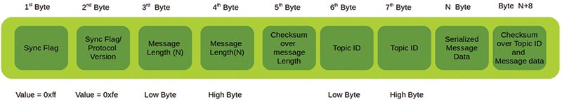
Figure 1. Rosserial packet structure.
The first byte is called Sync Flag which is used to synchronize the communication between ROS and the device. Its value will be always 0xff. The second byte or Protocol Version/Sync Flag tells you if the ROS version we are using is before ROS Groovy or after Groovy. The value will be 0xfe after ROS Groovy and will be 0xff up until Groovy. The third and fourth bytes represent the length of the message which is on the packet, and the fifth byte is a checksum of the message length. The sixth and seventh bytes are dedicated for Topic ID. The Topic ID from 0-100 is reserved for system functions. The remaining bytes are used for serial data and its checksums.
The checksums of the length of the packet and data is computed using the following equation:
255 - ( (Topic ID Low Byte + Topic ID High Byte + data byte values) % 256)
The communication between the serial device and PC will start from the PC side, which will send a query packet for getting the number of topics, names, and types of topics from the Arduino/serial device side. When the Arduino gets this query packet, it will reply to the PC with a series of response packets. The response packet will consist of the following entries:
uint16 topic_id
string topic_name
string message_type
string md5sum
int32 buffer_size
This series of responses will be in the rosserial_msgs/ TopicInfo messages. When a response is not getting answered from the serial device, the query will resend from the PC side. The synchronization between ROS and the serial device is handled by sending timing information from the PC to the particular device.
The rosserial_client Libraries
The rosserial_client libraries (http://wiki.ros.org/rosserial_client) have a client side implementation of the rosserial protocol. The client can be an embedded microcontroller platform such as with an Arduino, ARM, or another serial device such as Xbee. It can run on any processor which has an ANSI C++ compiler and serial interfacing to a computer running ROS. There are several rosserial_client library packages out there for specific platforms. Here are some of those rosserial_client libraries:
- rosserial_arduino: This package helps you build an Arduino library called ros_lib which can work as a rosserial_client library for Arduino. We can include this library for writing Arduino-ROS client nodes. This package helps us create a rosserial client on most of the Arduino platforms – especially the Uno, Mega, and Leonardo.
- rosserial_embeddedlinux: This package enables us to run rosserial_client on embedded Linux systems (like routers, etc.).
- rosserial_windows: ROS is not completely ported to Windows. If we have to communicate with any Windows application, we can use this package to communicate from the Windows client to ROS.
- rosserial_mbed: Most of the ARM controller based boards support mbed (hardware abstraction layer) programming, which is similar to Arduino programming. We can either program mbed boards using an online compiler, or offline using a gcc4embed (https://github.com/adamgreen/gcc4mbed) project. The offline compiler can only work with a limited number of boards, but the online compiler can use new boards which support mbed.
- rosserial_tivac: The Tiva C Launchpad is another controller board from Texas Instruments which runs on 80 to 120 MHz. The latest boards are 123GXL and 129XL, and support the Arduino-like IDE (integrated development environment) called Energia (http://energia.nu). We can program Tiva C using the Arduino programming language called Wiring (http://wiring.org.co).
After writing the rosserial node into a serial device, we have to run another node on the PC side to encode/decode the serial data. There are some packages for doing this process. Those are:
- rosserial_python: This package is commonly used for rosserial communication. You have a Python node which can connect to the serial device and receive serial values from the device. It will decode serial packets and generate ROS topics and services which will be available on the PC side. This package is stable and recommended for PC applications.
- rosserial_server: This is actually a C++ implementation of a rosserial receiver and can be used for high performance applications. The features of this node are less compared to rosserial_python.
- rosserial_java: If you want to interface ROS with an Android, this is the best choice.
We are going to use rosserial_python on the PC side.
Required Components
These are the two hardware components we need to start with our Arduino-ROS programming:
- Arduino Mega 2560 (https://www.arduino.cc/en/Main/ArduinoBoardMega2560)
- USB B-type cable
To start interfacing our Arduino to ROS, the first procedure is to install ROS on the PC itself.
Installing ROS on Ubuntu 16.04 LTS
For working with an Arduino, we can set up a new ROS distribution which is ROS Kinect Kame on Ubuntu 16.04 LTS. I’ll also give you the instructions to set ROS Indigo on Ubuntu 14.04 LTS.
You can either install Ubuntu on a real PC or VirtualBox (if you want to work from Windows).
Here are the procedures to set up Ubuntu 16.04 LTS and ROS Kinect Kame:
- Download Ubuntu 16.04 LTS from http://releases.ubuntu.com/16.04 burn it to a disc or write it to a USB drive using unetbootin (https://unetbootin.github.io) to install it to a PC. You can also install Ubuntu on VirtualBox (https://www.virtualbox.org/wiki/Downloads). The complete Ubuntu installation tutorials are available at www.ubuntu.com/download/desktop/install-ubuntu-desktop.Note that in the VirtualBox setting, the video memory should be high, and you should install the VirtualBox Guest Add-ons after the Ubuntu installation.
- Next, install ROS on Ubuntu. For detailed instructions on how to install ROS Kinect on Ubuntu 16.04 from the ROS website, go to http://wiki.ros.org/kinetic/Installation/Ubuntu. If you are interested in ROS Indigo, please use http://wiki.ros.org/indigo/Installation/Ubuntu instead. Also note, instead of Ubuntu 16.04, you need 14.04 LTS to install ROS Indigo.
- You will need the ROS-Kinetic-Full desktop installation for this project.
Once the ROS installation is complete, run the roscore command to check that everything is working fine. A screenshot of this command is shown in Figure 2.
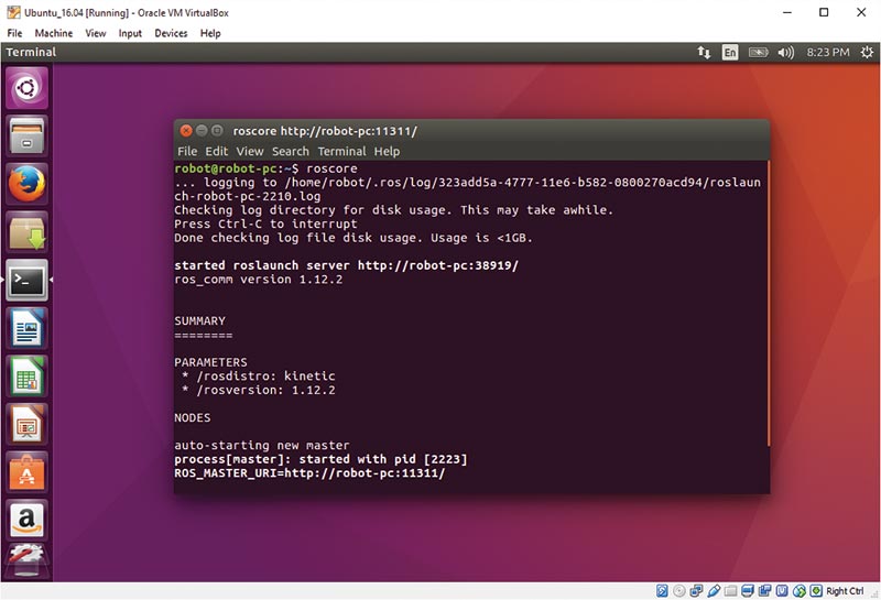
Figure 2. Running roscore.
Installing the Rosserial Interface Package on Ubuntu
After setting ROS on Ubuntu, we have to install rosserial packages in ROS. Installing a package can be done in two ways:
- Installation through apt-get which will install pre-built binaries.
- Installation through compiling source code.
The easiest way to install packages is using apt-get but in the latest ROS versions, most of the packages may not be available as binaries. In that case, we can create a ROS work space and download the source packages and install it. Here’s the procedure to build a rosserial package in ROS Kinect:
1. On your terminal, create an empty folder for the ROS workspace. You can give it any name; I am using rosserial_ws:
$ mkdir -p ~/rosserial_ws/src //Creating a folder called rosserial_ws, and src folder inside the workspace folder
$ cd ~/rosserial_ws/src //Switch to src folder
$ catkin_init_workspace //This will initialize a catkin workspace
$ git clone [url=https://github.com/ros-drivers/rosserial ]https://github.com/ros-drivers/rosserial [/url]; //Cloning latest source code of serial package in src folder
$ cd ~/rosserial_ws //Change into workspace folder
$ catkin_make //Command to build the entire workspace
2. The catkin_make command will build all the packages inside the workspace and it generates additional folders like ‘build’ and ‘devel.’ The build folder contains build logs and the devel folder contains shell scripts and generated executables. For making this package visible to the ROS environment, you have to source one of the shell scripts in the devel. The following command will do this job:
$ echo “source ~/rosserial_ws/devel/setup.bash” >>~/.bashrc
$ source ~/.bashrc
Congratulations!! You are done with the source installation of rosserial packages!! If you are trying to install using apt-get, you can use this command:
$ sudo apt-get install ros-kinectic-rosserial
Note: If it fails, please switch to the source installation. If you are working with ROS-Indigo, you can directly install it using the following command:
$ sudo apt-get install ros-indigo-rosserial
Setting the Arduino IDE and ROS Client Library
In this section, we are going to set the Arduino IDE on Ubuntu 16.04. Arduinos can be easily programmed using their simple IDE. This IDE can be downloaded from the Arduino website and is available for popular OS platforms. Go to https://www.arduino.cc/en/Main/Software. We can either download the IDE from this website or install it via the Ubuntu software package manager. Downloading directly from the website will give you the most current version.
For installing the Arduino IDE from the Ubuntu software package manager, use this command:
$ sudo apt-get install arduino
After installation, you can run the command arduino in your terminal, or if you are working with binaries downloaded from the website, extract the archive and you can see an executable called arduino. Simply execute it using this command:
$ ./arduino
If everything works fine, the Arduino IDE will pop up and you will see the screen in Figure 3.
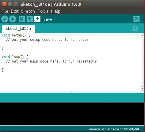
Figure 3. Arduino IDE.
Congratulations! You have successfully set up the Arduino IDE in Linux. Our next procedure is to set up the rosserial Arduino library.
Setting Up ros_lib in the Arduino IDE
After setting up the Arduino IDE, we have to create an Arduino-ROS library for writing Arduino-ROS nodes. Here are the steps for setting it:
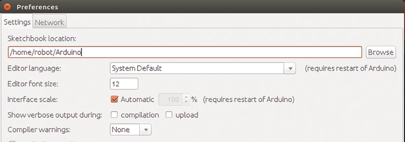
Figure 4. Arduino Preference.
- Navigate to File -> Preference in the Arduino IDE, and find the sketchbook location (Figure 4). Go to the sketchbook location and find the folder called libraries. If it is not there, you can create a new one. This is the location where we are going to create the Arduino-ROS library.
- To build the Arduino-ROS library, open a new terminal and run:
$ roscore - Open a new terminal in arduino_sketchbook_folder/libraries and enter the command shown in Figure 5. This command will generate the ros_lib library which consists of embedded equivalent messages of actual ROS messages and ROS serial client APIs. Note: It may show an error during generation. Just ignore the error messages. For some ROS messages, embedded equivalent conversions may not be possible.
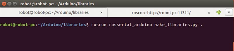
Figure 5. Generating Arduino ros_lib.
If the ros_lib is now properly in the folder, you may get the examples of ros_lib from the following option (refer to Figure 6):
File -> Examples -> ros_lib
Now, we can work on simple examples using it. We can start with a Blink LED code. Using this example, we can toggle the state of the LED whenever we publish a value to a topic. Here is how we do that.
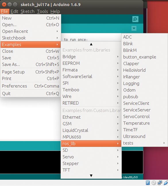
Figure 6. Arduino ros_lib examples.
Setting the Board Name and Serial Device in the Arduino IDE
You can either program Arduino in the real Ubuntu system or VirtualBox. If you are working with a PC, just plug in the Arduino device and when you plug the Arduino in Ubuntu, it will act as a serial device and the Linux kernel will load the USB to serial driver.
Use a Linux terminal and execute dmesg or dmesg | grep tty. The dmesg will show the kernel logs and we can find the serial device corresponding to the Arduino. The output of dmesg & dmesg | grep tty is shown in Figure 7 and Figure 8.
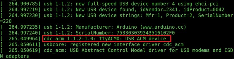
Figure 7. Linux kernel messages.
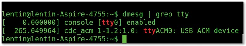
Figure 8. Dmesg and grep messages.
The device name for the Arduino is ttyACM0. It may be different for each system.
ROS Running on VirtualBox from Windows
If you are working from Windows and VirtualBox, you first need to install the proper driver of the Arduino for Windows. The drivers are available in the Arduino installation folder itself. You may need to download “Arduino for Windows” to get this driver. After installing the driver, use the Windows Device Manager to check the serial port number of the Arduino. If everything is set, it should look like Figure 9.
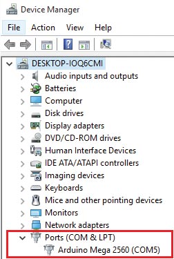
Figure 9. Windows Device Manager.
You will only see this if the Arduino drivers are properly installed. After setting the drivers, you can share this serial device in VirtualBox.
Launch VirtualBox and got to Settings -> Serial Port. Share the real port in the guest OS as shown in Figure 10.
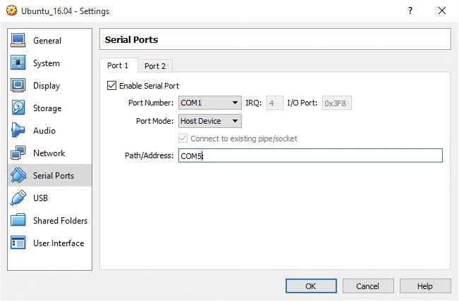
Figure 10. Sharing a serial port in VirtualBox.
Here, the actual device is COM5:. In the guest device, it is going to be COM1 which corresponds to ttyS0 in Linux.
Setting the Board Name and Port in the Arduino IDE Running on VirtualBox
After getting the serial port number of the Arduino, we should set these parameters inside the Arduino IDE. Here is how we do that.
To set the board name, go to the IDE Menu Tools ->Board ->Arduino Mega 2560. Also set the port name from Tools -> Port ->ttyS0.
If you are working from a PC, the port will be ttyACMO. If you working from VirtualBox, recall the port that we assigned was ttyS0. Test the connection between the Arduino and VirtualBox by burning a sample sketch called Blink:
File -> Examples -> Basics -> Blink
Load the sketch, compile it, and upload it to the board.
Note: If you are getting a permission denied error or something similar, you can do the following fix to solve it.
These commands will allow us to add a current user into a group called dialout. This group user can access a serial device without permission:
$ sudo usermod -a -G dialout <username>
To set the read/write permission to the existing serial device, use this:
$ sudo chmod 666 /dev/ttyACM0 or ttyS0
If everything is working great, upload an Arduino-ROS client code for blinking an LED on the Arduino board. You will get it from File -> Example -> ros_lib -> Blink.
First Project: Blink an LED
/*
* rosserial Subscriber Example
* Blinks an LED on callback
*/
// Arduino – ROS headers
#include <ros.h>
#include <std_msgs/Empty.h>
//Creating a Nodehandle object
ros::NodeHandle nh;
// Creating a callback for the topic toggle_led, whenever a value come through this topic, this callback will execute
// The callback will toggle the state of LED which is on PIN 13
void messageCb( const std_msgs::Empty& toggle_msg){
digitalWrite(13, HIGH-digitalRead(13)); // blink the led
}
//Creating a subscriber with a name toggle_led, and its callback
ros::Subscriber<std_msgs::Empty> sub(“toggle _led”, &messageCb );
//Setting PIN 13 as output and initializing ROS node and subscriber object
void setup()
{
pinMode(13, OUTPUT);
nh.initNode();
nh.subscribe(sub);
}
// Spining the node each times to listen from the topic
void loop()
{
nh.spinOnce();
delay(1);
}
In this code, we are creating a subscriber ROS node inside the Arduino, which will listen to a topic called toggle_led. Whenever a value publishes this topic, the LED will change its state.
Upload this source code to the Arduino and let’s see how to publish values to this topic. First, go to a terminal and run:
$ roscore
Run the rosserial node on the PC side to encode/ decode Arduino messages:
$ rosrun rosserial_python serial_node.py <serial_dev_name, eg: /dev/ttyACM0 )
If this command is okay, you will get a message like that shown in Figure 11.
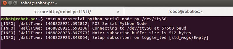
Figure 11. ROS-Python serial node.
If the node is working well, enter the following command:
$ rostopic list
It will list out the topics on the ROS system. If everything is correct, you may get output that looks like Figure 12.
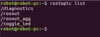
Figure 12. ROS topic list.
Yes! We did it! We got the topic from the Arduino-ROS client. Now, to publish a value to this topic, use this command:
$ rostopic pub toggle_led std_msgs/Empty –once
Take a look at Figure 13.
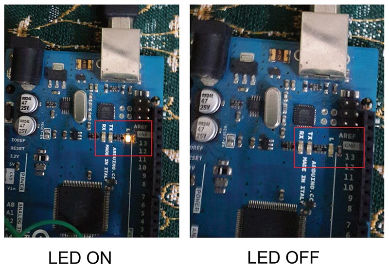
Figure 13. LED toggle.
You can find more examples of ROS-Arduino interfaces at http://wiki.ros.org/rosserial_arduino/Tutorials.
Interfacing an MPU-9150 on an Arduino Using ROS Kinetic
Next, we’ll discuss a more complicated example using ROS and an Arduino. In this example, we are going to interface an IMU (inertial measurement unit) called the MPU-9150 to an Arduino Mega 2560, and visualize its values on Rviz.
Required components include:
- Arduino Mega 2560
- USB B-type cable
- MPU-9150 breakout board
- Breakout pin headers
- Arduino male-to-female jumper wires
Project Concept
The MPU-9150 is a popular IMU from a company called InvenSense (www.invensense.com). It has a built-in accelerometer, gyroscope, and magnetometer. It also has a motion processing unit called DMP (Digital Motion Processing) to fuse all three sensor data to get accurate orientation information. The MPU-9150 can be easily interfaced to an Arduino using the Arduino library.
After retrieving the orientation information from the sensors, it will send it to ROS via the ROS-Arduino interface. The Arduino-ROS client will publish an IMU ROS message and also publish Transform (TF) information. The TF data can be directly visualized on Rviz.
Soldering MPU-9150 Pin Headers
When you purchase the MPU-9150, you will get its pin headers which have to be soldered to the breakout board. Figure 14 shows how the pin headers are soldered. These pins can be interfaced to an Arduino using the male-to-female jumper wires.
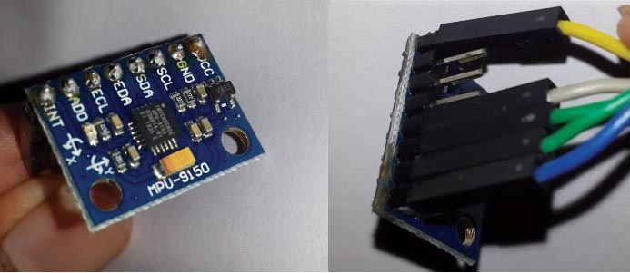
Figure 14. MPU-9150 breakout board.
You should be very cautious while soldering because excessive heat can damage the main IC on the board. You should keep the pin header alignment perpendicular to the board while soldering. If the pin alignment is not proper, we can’t mount the IMU into a breadboard.
After soldering, we can connect the IMU module using the M/F jumper wires. The female connector can be used to attach the IMU, and the male connector can be used for the Arduino. Figure 15 shows the circuit of the IMU to the Arduino 2560.
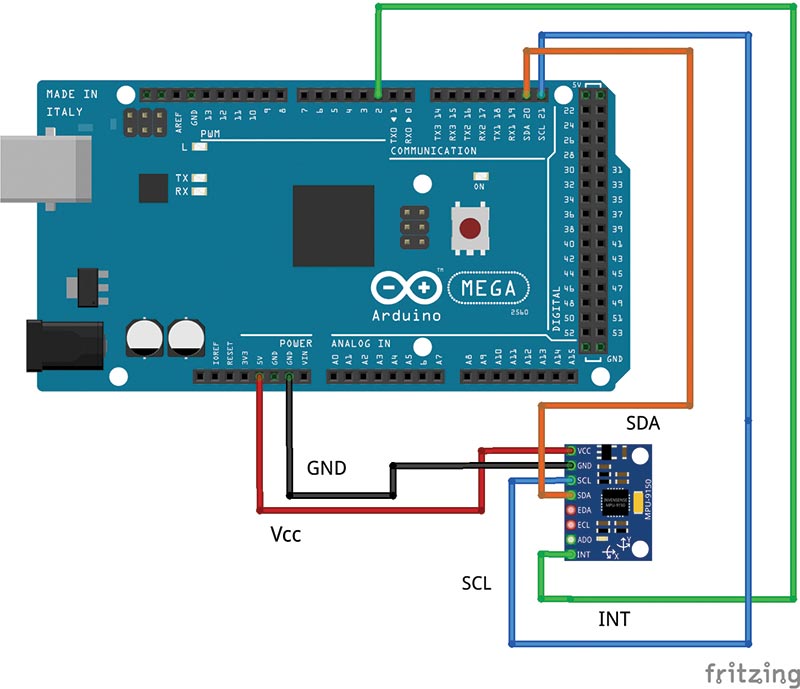
Figure 15. MPU-9150 Arduino interfacing circuit.
Programming the Arduino
To start programming with the Arduino, we first need to download the Arduino library for the MPU-9150. We can download it from https://github.com/sparkfun/MPU-9150_Breakout. Copy the content of the firmware folder to the <arduino_sketchbook location>/libraries folder. Open the Arduino IDE; if everything is set, you should get what you see in Figure 16.
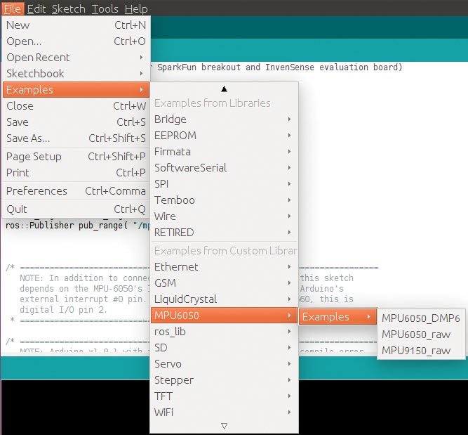
Figure 16. MPU-9150 library on Arduino IDE.
If you get this, you can copy the ROS_IMU interfacing code to the Arduino IDE; compile and burn it to the Arduino. The complete explanation of the code is commented in the code itself.
After burning the ROS_IMU code into the Arduino, start roscore on the PC side. Also, the ROS Python serial node can give you your own device name by using this command:
$ rossrun rosserial_python serial_node.py /dev/ttyACM0
If everything is working fine, you will get a message like that shown in Figure 17.
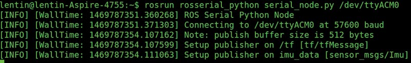
Figure 17. Running rosserial node.
You can list out the topics after running the above command. You may get new topics such as /imu_data, /tf as in Figure 18.
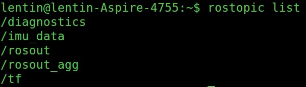
Figure 18. Listing topics.
You can also inspect each topic. The imu_data can be echoed using the following command:
$ rostopic echo /imu_data
When you echo the topic, you may get values like those in Figure 19.
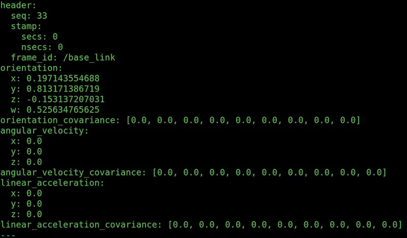
Figure 19. Echoing imu_data.
You can also echo the /tf using this command:
$ rostopic echo /tf
Figure 20 shows a typical output of the tf topic.
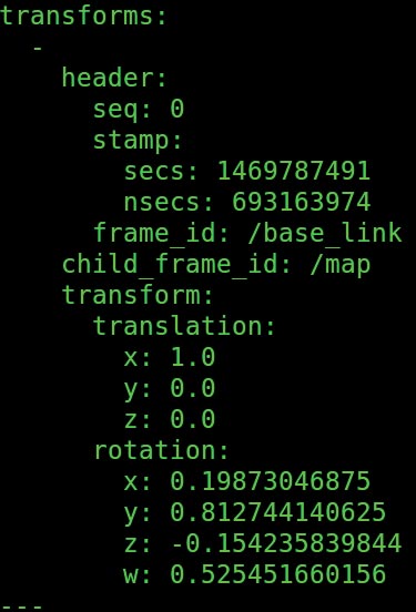
Figure 20. Echoing TF.
After checking these topic values, we can display the TF data inside Rviz as you can see in Figure 21.
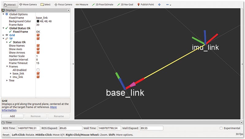
Figure 21. Visualizing TF.
The screenshot shows the imu_link with respect to base_link which is a static link. The IMU link is placed one unit away from base_link. You can move the IMU by using your hand to change its orientation. You can see the same orientation inside Rviz as well.
Congratulatios! You are done interfacing one of the best IMUs available on the market to ROS! You can now use it for various applications such as robot control and teleoperation.
Conclusion
That wraps up our basic tutorial session on an ROS-Arduino interface. We installed ROS and set up ROS serial packages to communicate with an Arduino. We have successfully set up the interface and then performed a basic Blink code using this interface. We also completed a complex example called ROS-IMU interfacing. SV
Article Comments