Perimeter Sensing Options
By John Blankenship View In Digital Edition
Mobile robots need perimeter sensing. There are many options, including digital and analog, IR and ultrasonic — even a laser could be in your future. Understanding the limitations and advantages of various choices can help you improve the functionality of your robot.
Mobile robots often utilize perimeter sensing in order to perform tasks such as avoiding obstacles, hugging walls, and navigating cluttered environments. Some perimeter sensors — such as the Sharp GP2Y0D810Z0F shown in Figure 1 — are limited in that they merely provide a true/false indication of the presence of a detected object.
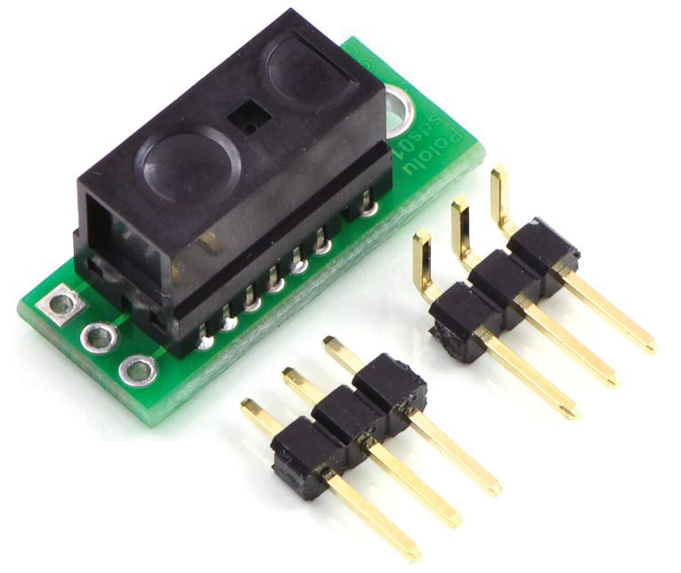
FIGURE 1.
These sensors are often referred to as digital sensors because their output is zero or one. In this case, objects can only be detected when they are within a 2 to 10 cm range.
Ranging sensors, on the other hand, are devices that can provide a distance measurement to objects that have been detected. Such sensors generally utilize infrared or ultrasonic waves to measure the distance to objects. The measured distance supplied by these sensors can take many forms. It might, for example, be a voltage whose amplitude is related to the distance measured. The data might also be provided using some form of a serial transmission (USB, I2C, etc.). Even though serial transmissions are digital, ranging sensors are often referred to as analog sensors because the output from them is not a true/false condition.
Figure 2 shows an IR-based Sharp analog sensor (GP2Y0A21YK0F) capable of measuring distances up to 80 cm.
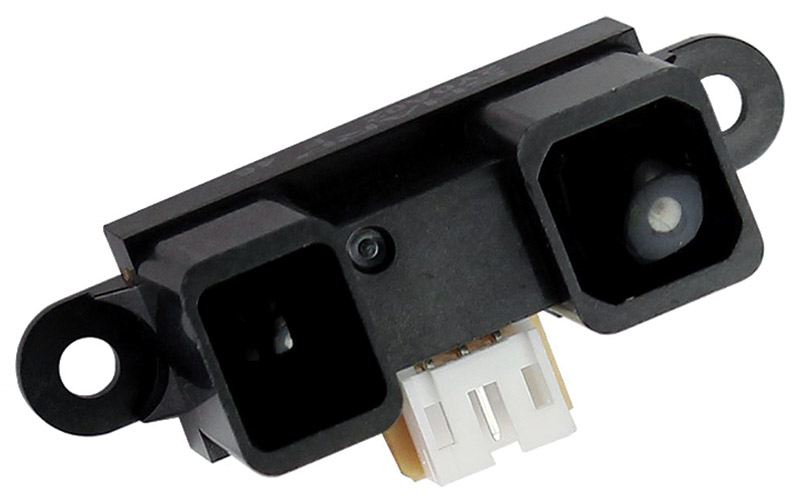
FIGURE 2.
The output from this sensor is a voltage as indicated in Figure 3, which means you must use an ADC (analog-to-digital converter) to obtain the reading. There are several things we can learn from this graph.
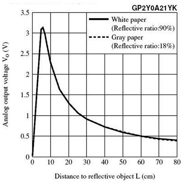
FIGURE 3.
First, objects nearer than 5 cm can appear to be farther away because the voltage generated is the same as a more distant object. Also notice that the main part of the graph has an inverse relationship with the distance (the voltage decreases as the distance increases). Finally, observe the non-linearity of the voltage/distance relationship. This means calculations are necessary to extract the actual distance.
The Parallax PING))) sensor shown in Figure 4 utilizes sound waves to measure distances up to three meters.
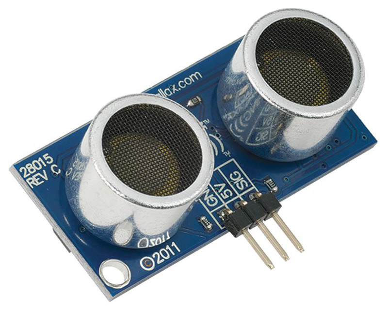
FIGURE 4.
In order to obtain distance readings from ultrasonic sensors, you generally must write a program that triggers the unit to send out a burst of ultrasonic sound. The program then counts the time it takes for the wave to hit a remote object and reflect back to the receiver, and then uses that time to compute the distance to the object. This calculation is linear, so it is much easier than that required for the IR sensor of Figure 2.
The signal indicating the wave has been received is a digital (true/false) indication, but again, these sensors are often referred to as analog because the data they ultimately provide is a variable quantity.
These two examples demonstrate why it can be more difficult to obtain ranging information than to simply detect the presence of an object with a digital sensor. When distance data is not needed, the low cost and ease-of-use of digital sensors can make them attractive — especially for less sophisticated robots or beginning hobbyists. Even ranging sensors, however, have their own limitations.
IR sensors can only sense objects that reflect light back to them, so dark objects that absorb light or objects with surfaces that greatly disperse light can be difficult to detect. IR rangers are particularly susceptible to this problem because the amplitude of the IR wave is small to begin with and it decreases with the distance being measured.
Ultrasonic sensors generally require software routines to measure the time for sound waves to bounce off objects and return to them. The linearity of the time-distance relationship makes it easy to obtain fairly accurate readings, but ultrasonic sensors can have trouble reliably detecting soft objects (such as stuffed animals, curtains, etc.) that absorb sound waves.
Both IR and ultrasonic sensors can have trouble detecting surfaces that are not somewhat perpendicular to their beams because angled surfaces can reflect the waves off to the side instead of back toward the sensor. In addition, the IR and ultrasonic sensors generally used for robotics can only reliably measure distances of 3-10 feet.
Often, an object that is difficult to detect with ultrasonics is easily seen with an IR-based sensor (and vice versa). For that reason, there are advantages for giving your robot both types so it can spot objects detected by either sensor. Parallax provides a dual-mounting bracket for IR and ultrasonic sensors (Figure 5) to help facilitate such an arrangement.
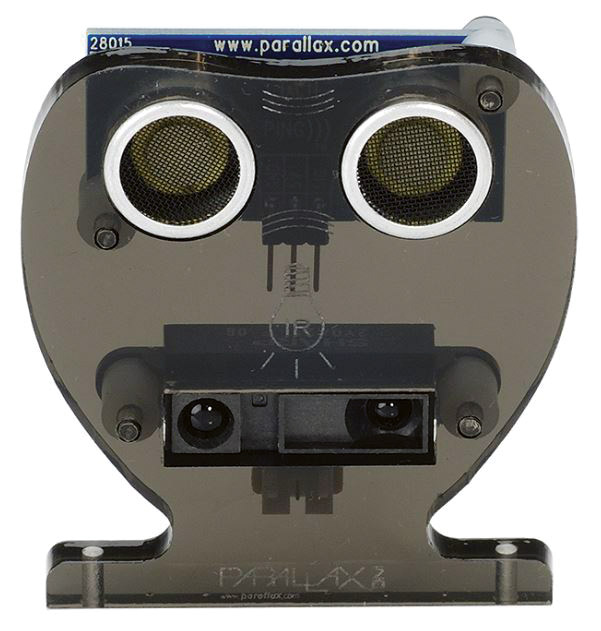
FIGURE 5.
Even with all their limitations, IR and/or ultrasonic ranging sensors can provide reasonably accurate (within 1/2 inch or so) and reliable information, especially in a controlled or known environment. This — plus the fact that rangers cost only slightly more than digital sensors — makes them an excellent choice for many hobbyists. Sometimes though, better accuracy, greater distances, and more reliability are needed.
Laser ranging sensors are significantly more expensive than IR or ultrasonic, but they solve many problems. Lasers generally have no trouble detecting dark or soft objects, and — perhaps even more important — they easily detect angled surfaces that can confuse IR and ultrasonic sensors. Furthermore, their detection range can be 50 times greater than IR and ultrasonic rangers.
The accuracy of a laser sensor (typically around 1 cm) is not significantly better than other types of rangers, but that’s not the entire story. The readings from IR and ultrasonic sensors often bounce or jitter around the actual value. The distance to a stationary object might, for example, be reported as 10 inches, then 9, then 11, then 10, etc. Such individual readings are obviously not truly accurate, but an accurate reading can often be obtained by averaging the readings over time. The readings from laser rangers — by comparison — are far more stable and repeatable than other types.
For many applications, a laser’s capabilities are worth the higher price. The extended range of a laser, for example, can greatly enhance a robot’s navigational behaviors because it can map its environment and more precisely determine its location by accurately measuring the distance to known objects and distant walls.
Lasers don’t just improve the standard mobile robotic behaviors we are all familiar with. They also make it simpler to deal with new technologies. For example, the extended range of a laser sensor can make it easy to determine the altitude of a drone, and the speed and accuracy of the measurements can enhance the ability to land autonomously.
Interfacing with many laser rangers can be difficult, but Parallax has made it easy with its new line of laser-based sensors. Figure 6 shows a typical model in their SF10 series which can measure distances up to 100 meters.
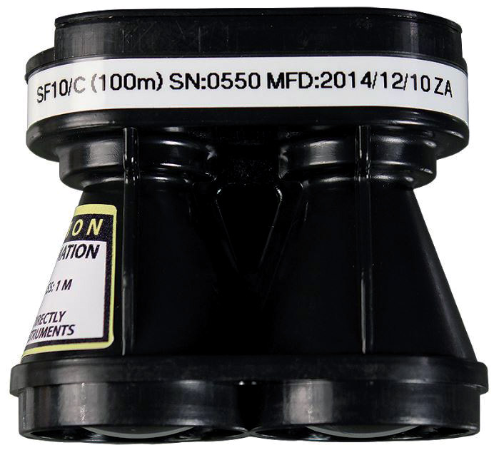
FIGURE 6.
Figure 7 shows the SF02 which has a maximum range of 50 meters.
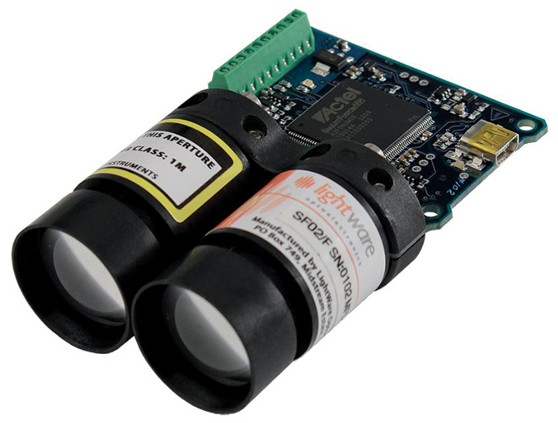
FIGURE 7.
Both of these lasers were designed to be used as altimeters for small aircraft, but they also make excellent perimeter sensors for mobile robots.
No matter which model you choose, a major advantage of the Parallax lasers is their variety of interfaces which allows them to connect with almost any processor. The interfaces include USB, analog, CMOS serial, and I2C. Another advantage of these lasers is that they can be configured to meet your specific needs. Let’s look at an example to illustrate this point.
I felt my Arlo robot (see the series, The Robot You’ve Always Wanted, that started with the January 2015 issue of SERVO) could be enhanced by adding a ranging laser to his turret. For a variety of reasons, I chose the SF02. Figure 8 shows it mounted on Arlo’s turret which also supports an IR sensor, an ultrasonic sensor, a beacon detector, and a webcam. My goal was to replace the IR sensor with the SF02.
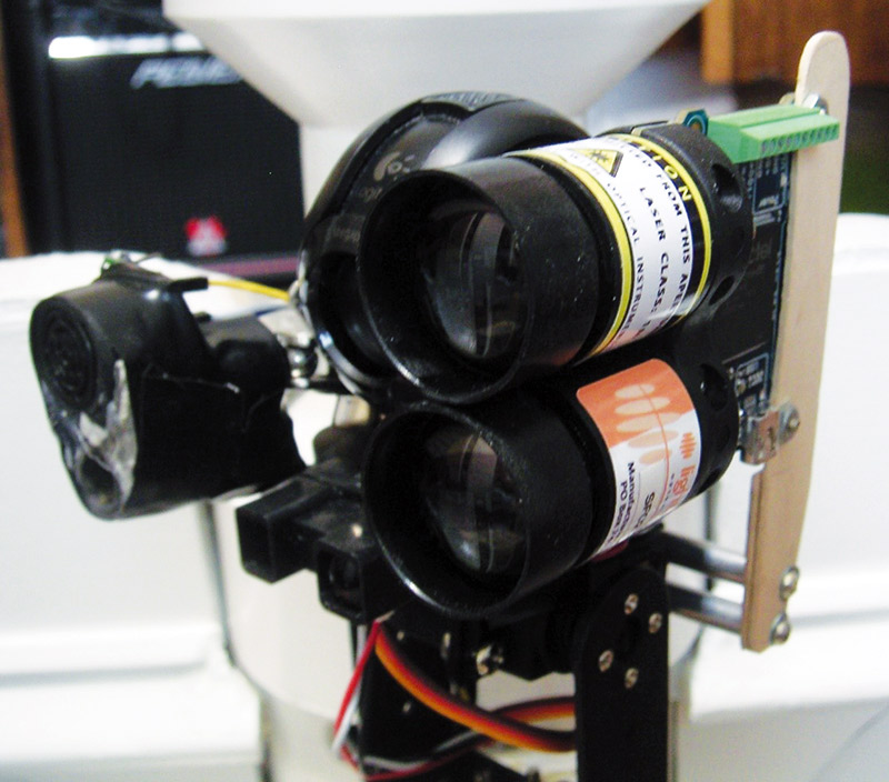
FIGURE 8.
Arlo’s original IR sensor produced an analog output, so I was pleased that the SF02 also had an analog option. Arlo’s original software obtained the distance data with a 10-bit ADC, but the number was scaled to eight bits. I was worried that eight bits would not be enough for the laser’s greater range and accuracy, but the SF02’s ability to be customized made it easy to solve the problem.
Parallax provides a program called the Lightware Terminal that lets you configure the SF02 in a variety of ways as detailed by Figure 9. The configuration options available on the SF02 proved to be exactly what I needed.
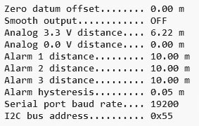
FIGURE 9.
The SF02 outputs a voltage between 0 and 3.3 volts (with 10 bits of precision) to indicate the distance measured. You can configure this output so that a full reading of 3.3 volts indicates any valid distance. If the analog output is read with a 10-bit ADC, the resolution can be exceptional, but obviously it won’t fit in the eight bits needed to maintain compatibility with my original application.
I determined that a resolution of one inch was acceptable for my needs, which means that an eight-bit byte could hold distance measurements up to 255 inches. This distance (more than 21 feet) was also deemed acceptable for an indoor robot such as Arlo. Therefore, I set the laser’s maximum distance to 6.22 meters (see Figure 9) which is 255 inches.
Most ADCs assume their input voltage has a range of 0V-5V. Remember, though, that the output from the laser is only 0V-3.3V. Since 3.3/5 is essentially 2/3, we can effectively make the voltage a full range reading if we multiply it by 3/2. The reading will still be 10 bits, though, so we can shift it right twice (or divide by 4) to create the desired eight-bit number.
Both of these operations together simply multiple the acquired reading by 3 and divide that total by 8. This action proved to produce an extremely stable reading with reasonable distance and accuracy. It also shows the advantage of being able to configure the maximum range of the laser.
If your robot needs more accuracy or to be able to measure greater distances, there are easy modifications. Making the maximum range 12.44 meters will let the laser measure more than 40 feet, but each unit in the eight-bit answer represents two inches.
Reducing the range to 3.11 meters will improve the accuracy to 1/2 inch, but you will only be able to measure out about 10 feet. All things considered, the 6.22 meter range and one inch accuracy seems to be a good tradeoff.
Of course, if you want to use a two-byte value for the laser reading, you can get both longer distances and improved accuracy.
The ability to configure Parallax’s laser sensors should not be taken lightly. As Figure 9 shows, you have many options. You can specify an offset to ensure, for example, that a zero distance is reported at your robot’s perimeter. You can even tell the sensor to smooth any jitter by providing you with an average of multiple readings. My experience with the SF02 showed no need for the averaging, but it is a nice feature when extreme stability is needed.
It is worth mentioning that the light emitted from a ranging laser can damage your eyesight if you look directly into the beam. For that reason, you should carefully evaluate the safety needs of any project that utilizes a laser.
The higher cost of adding a laser to your robot does not make sense for every application, but it is a viable option when your situation requires longer distances and improved reliability.
Knowing the advantages and limitations of various perimeter sensing options can help you improve the functionality of your next robot. SV
Article Comments