Little Arduino Robot Hand
By Peter Ohlmus View In Digital Edition
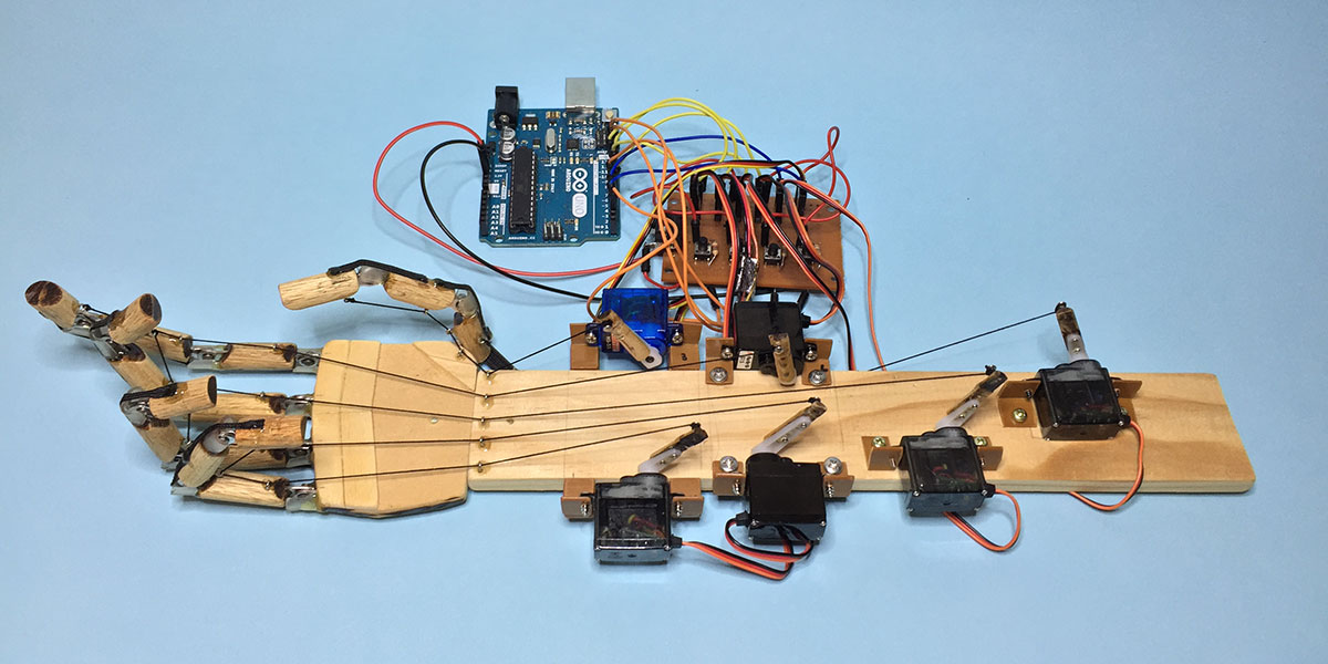
When I was on holiday, I made an inexpensive little robotic hand (Figure 1) using bits and pieces I found at various shops, along with the very cool Arduino microcontroller.
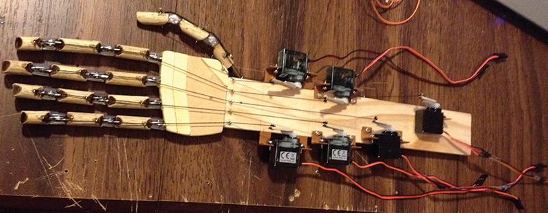
FIGURE 1. The little Arduino robot hand.
I have always loved playing with electronics and pulling things apart to see how they work. I have been assembling and playing with radio controlled vehicles and servos since I was about eight. So, I was quite excited when I noticed an Arduino Experimenter’s Kit at my local electronics store. After some online research, I was surprised and motivated by the possibilities I could pursue.
Initially, I thought about making a bipedal robot using micro servos as I’d been watching those classic cool Taiwanese robot fighting videos on YouTube. This changed quickly, after I began to imagine the prospect of mimicking hand movements, and achieving this cheaply using common materials and fast reliable servos. Thus, a da Vinci inspired robotic hand project was conceived!
It was my first play with the Arduino and writing code to control servos. To an experienced person, the wooden hand might look simple, but it demonstrates some fundamentals of servo control, Arduino programming, and mechatronics. Plus, it’s a fun adventure sourcing your own materials, thinking about solutions, putting it altogether, and seeing the final working product — as well as thinking of improvements and changes along the way.
All the parts used can be easily found in hardware and haberdashery stores, as well as local supermarkets. Once you’re comfortable with programming the Arduino, assembling and configuring it all is a satisfying experience.
How I Began
I didn’t spend a lot of time planning the project, and my first sketches and designs were quite basic; sketches of the finger joints and the size of the hand, along with placement of servos and the string I would use as tendons.
As the idea developed, I found it much easier just to source and make my own parts, and adjust them to work as I progressed. I basically modeled the wooden hand loosely on my own hand, with each finger segment roughly the same size as my own. If you’re looking to make something similar, I’d suggest you measure each segment of each finger of your hand to get a scale model.
I’m glad I didn’t have a 3D printer, as drawing, cutting, drilling, gluing, throwing out, and starting again adds to the enjoyment and creativity! Some good music or a good documentary to listen to in the background, all the requisite tools, enthusiasm, and plenty of time, and you’re good to go!
To start with, I chose a one meter length of 10 mm diameter dowel to act as the finger segments, cutting them to suit my sketches using my faithful Dremel Multipro. The blackened ends of the finger joints you see in my YouTube video were from the Dremel cuts — basically burning the wood as it cut.
Now, I needed knuckles, so I began looking in hardware stores for cheap but effective hinges which could join the finger segments together and enable them to move. I looked at small hinges, curtain rod connectors, scissors, and other potential donors, but it wasn’t until I was in the local supermarket and I saw a tea-infuser hanging on the wall that I knew I’d hit paydirt (or hingedirt)!
They were cheap, and each infuser had two pressed metal ‘hinges’ — two pieces of metal with a hole and pin that had been shot peened at one end. So, I bought 15 of them (to the eye-raised surprise of the checkout operator!), and low and behold oodles of infusers awaited their fate (Figure 2).
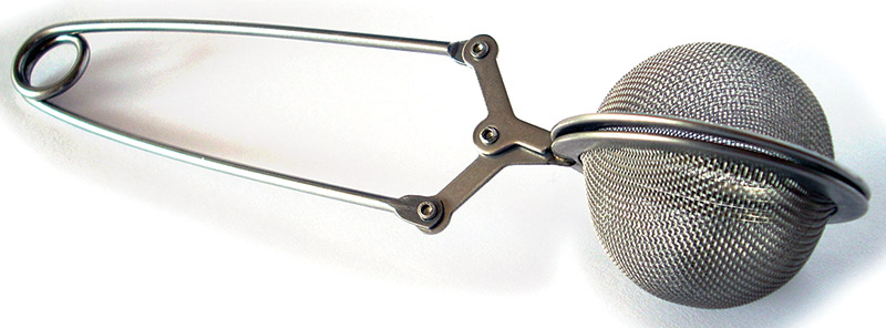
FIGURE 2. Tea infusers provided the hinges (knuckles).
I checked all of the hinges, and out of all 30 only about 18 moved smoothly and didn’t jam. I mean these are average quality pressed steel and not designed with tight tolerances in mind or to flop around smoothly.
The 18 that passed the test were more than enough for the three knuckles I needed for each finger.
A visit to the local haberdashery store and I found suitable thick cotton thread for tendons and some very small metal eyelets to be transformed into tendon guides (Figure 3).
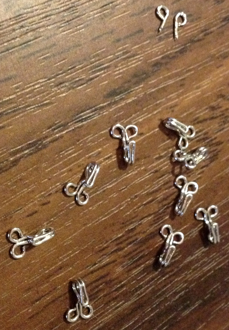
FIGURE 3. Eyelets to guide tendons. Note the 'cut-and-ready' pair at right.
I also found some narrow black elastic (like you would find in a pair of pants) which I wanted to use on top of each finger joint to provide resistance — to return the finger to an ‘open’ position (Figure 4).
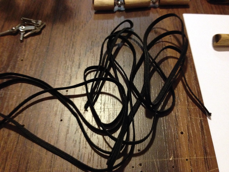
FIGURE 4. Elastic strip to provide resistance when fingers bend.
This elastic would also be applied to the thumb assembly during rotation/swiveling.
The ‘opening’ and ‘closing’ finger movement is actually termed ‘flexion’ and ‘extension.’ Bending the fingers toward the palm is flexion, or what I’m calling closing the finger; bending the fingers out straight away from the palm is extension, or what I’m calling opening the finger.
In between the finger segments (top of the hinge/knuckle), I used pieces of cut silicon tube. This provided an improvised form of cartilage to stop the finger segments bending back too far, and to also provide a small amount of natural cushioning.
For the palm and forearm sections, I used pine wood, MDF, and a few sliced up paddle pop sticks.
As far as moving the fingers went, I figured I’d need six servos: one for each finger and two for the thumb.
To control it, all I wanted was four inputs to give the hand four different functions, so I opted for a basic control board PCB (printed circuit board) that would have four buttons (for the inputs), and would be powered by a separate 5V power supply for the six servos.
Finally, there was the Arduino Uno which would be powered by my laptop.
This collection of bits and ideas all made a lot of sense and I jumped right into it — exactly what the enthusiastic tinkerer does on holidays!
I was now ready to build and program the little wooden hand.
Putting It All Together — Assembly and Soldering
I had the sketches of the finger segments done, so it was just a matter of marking the dowel and cutting all the segments. I cut the lower end of each palm-facing segment at 45 degrees, so the finger could close fully without the ends of each segment touching and not being able to travel further (Figure 5).
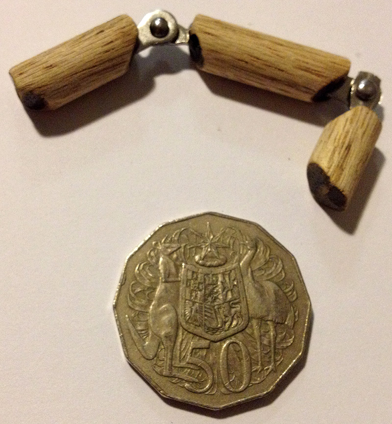
FIGURE 5. A nearly complete finger; note the 45 degree angle cuts on the lower sections so the finger can fully close.
I needed to cater to the knuckle/hinge, so there would be a gap of about 10 mm between two facing segments, after which I would drill holes in the finger segments.
The next step was to cut the hinges out of the tea infuser, leaving approximately 5 mm of shaft on either side of the hinge (Figure 6).
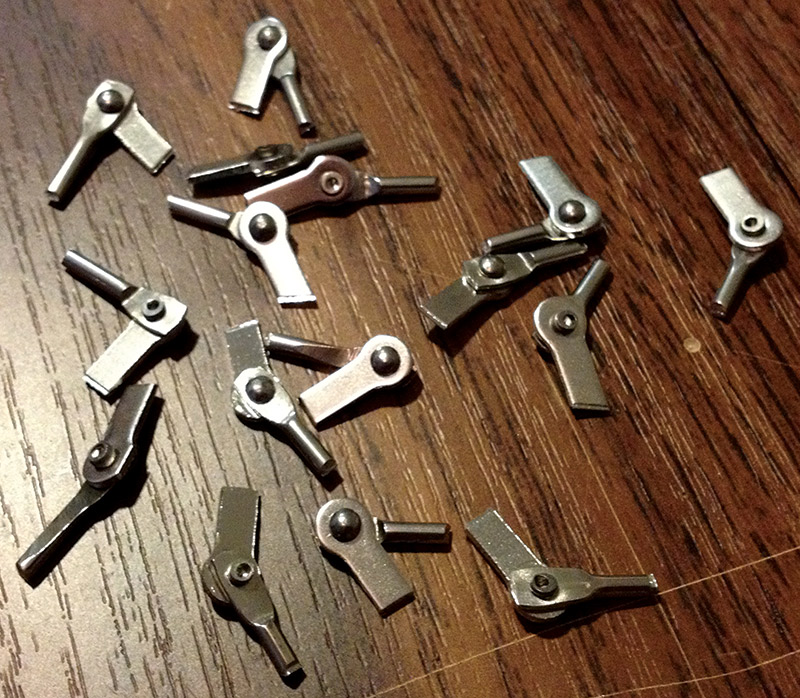
FIGURE 6. Hinges cut out from tea infusers and ready for use.
Use a drill bit that has a slightly greater width than the exposed tea infuser shafts, and then drill a hole into each end of each segment (except the finger tips). This is where the infuser shafts will go, allowing a small amount of space for the epoxy. Apply some epoxy to the holes and insert the shaft into the dowel. Make sure the hinges all line up as you don’t want to have wonky fingers bending at unusual angles. Also, be conscious of this placement especially if using quickset epoxy.
Now, it was time for the cartilage pieces. These need to be cut the same size as the gap between the finger segments (approximately 10 mm). Cut a piece of silicon the same length as the gap, then cut it in half.
You will want to epoxy one end of the silicone to the top half of one of the finger segments only; you don’t want to glue the two segments together (Figure 7).
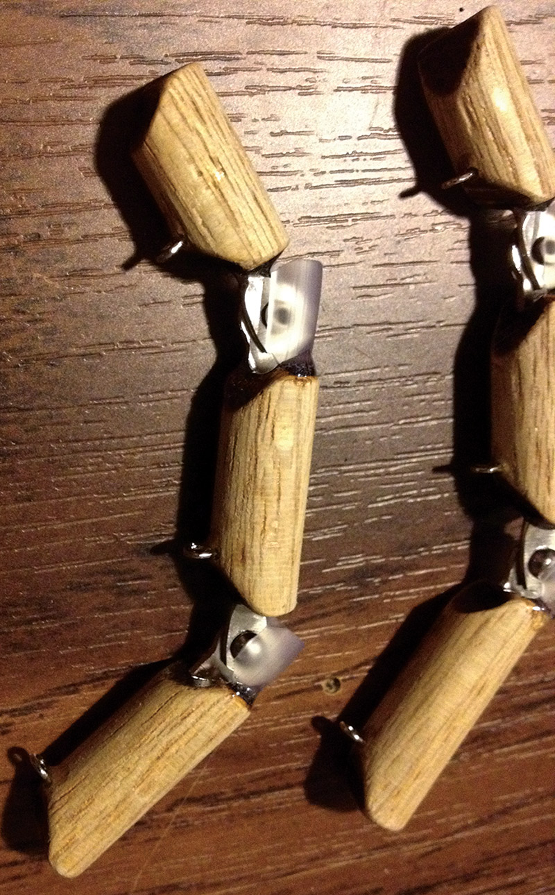
FIGURE 7. Tendon guides and cartilage cushion/stop added. Tip of finger is at left.
I then stretched the black elastic band pieces across the top (non-palm facing) of each finger segment, and held each end in place with rubber bands (you can also use small alligator clips). Then, I added a tiny drop of super glue under the elastic where it met the wood to hold it in place (Figure 8).
FIGURE 8. All four fingers with elastic resistance strip applied and curing.
When set, I tested there was the right amount of flex by opening and closing the finger, and if it felt right, I applied epoxy resin to the underneath of each end of the black band, trimming the excess off each end after the epoxy had set. If it didn’t feel right, the super glue bond was easily broken, allowing me to stretch it more or less and apply super glue again. I used Blu Tack to stick the now hinged-up finger to the table, while I placed and glued the elastic.
Now, on to the palm and forearm. I cut the piece of pine to 300 mm in length which was plenty for the forearm, then I traced my original palm sketch onto the piece of MDF and cut it out. Paddle pop sticks were added to the palm to simulate padding.
After lining up the end of the fingers with the end of the palm, I marked and drilled holes for the ‘finger-to-palm’ hinge, which was the last exposed hinge (Figure 9).
FIGURE 9. Earlier stages. Tracing out the shape of the palm on a piece of MDF.
Again, I used Blu Tack to hold the fingers in place while applying epoxy to the palm holes and hinge ends.
After completing the palm and the forearm, I attached them together with a flat piece of steel and moved onto the thumb connection point on the palm.
I had to figure out how my real thumb actually moved, and ended up attaching the completed thumb assembly at a 45 degree angle to the bottom corner of the palm. I drilled a hole in this point of the palm and also through the last thumb segment, then screwed them together with a small amount of play so the thumb assembly could swivel smoothly.
Elastic for the thumb was two-fold; where the thumb assembly itself has strips of elastic for each segment of the thumb, a single separate piece of elastic is also required to return the entire thumb assembly back to the open palm position.
I attached this piece of elastic to the thumb segment closest to the palm, then anchored it to the forearm. Two small pieces of metal were then screwed to the back of the palm to stop the thumb assembly from continuing to rotate (Figure 10).
FIGURE 10. The mechanics are complete. The final step was applying the thumb assembly return elastic.
Next in line were the tendon guide eyelets. For these, I basically just drilled small holes at the lower end of each finger segment, then cut an eyelet in half and glued the single eyelet loop into the hole. I repeated this on the palm, but had to align these final guides with the servo placement on the forearm (Figure 11).
FIGURE 11. Tendon guides on the forearm for all five digits. Not shown are the eyelets to swing the thumb assembly up.
An eyelet was added at the thumb segment closest to the palm. This would provide the anchor point to swivel the thumb assembly up and down. Another eyelet was added to the end of the forearm where it met the palm, right beneath the point where the thumb assembly was attached. This second eyelet would guide the thumb swivel tendon directly back to the servo.
A third eyelet was added further down the side of the forearm to keep the thumb swivel tendon from getting caught on the other servos.
One of the most important steps was mounting and aligning the servos. Each servo horn had to line up with the final tendon guides. So, I placed each servo and eyeballed the position, then made basic mounts using right angle plastic brackets, and drilled and screwed them into place.
You’ll note the staggered arrangement in the picture — this is because they couldn’t all be lined up next to one another or they just wouldn’t fit (Figure 12).
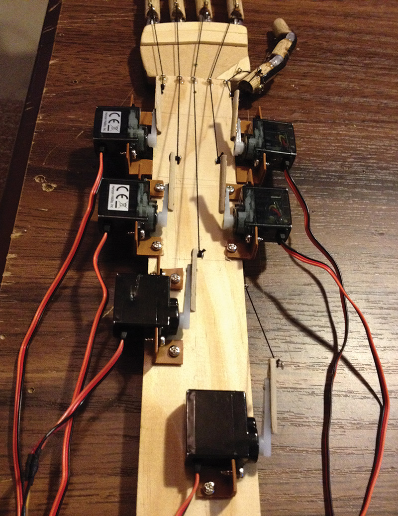
FIGURE 12. The complete mechatronic assembly. The servo at the bottom of the picture controls the thumb assembly swivel, with the tendon running underneath the servos on the right.
Once the servos were locked down, I tied the string to the fingertip eyelet of each digit, then fed the string down through all the eyelets until it reached its respective servo horn (Figure 13). With all hand parts now assembled, I moved to soldering all the components to the control board PCB.
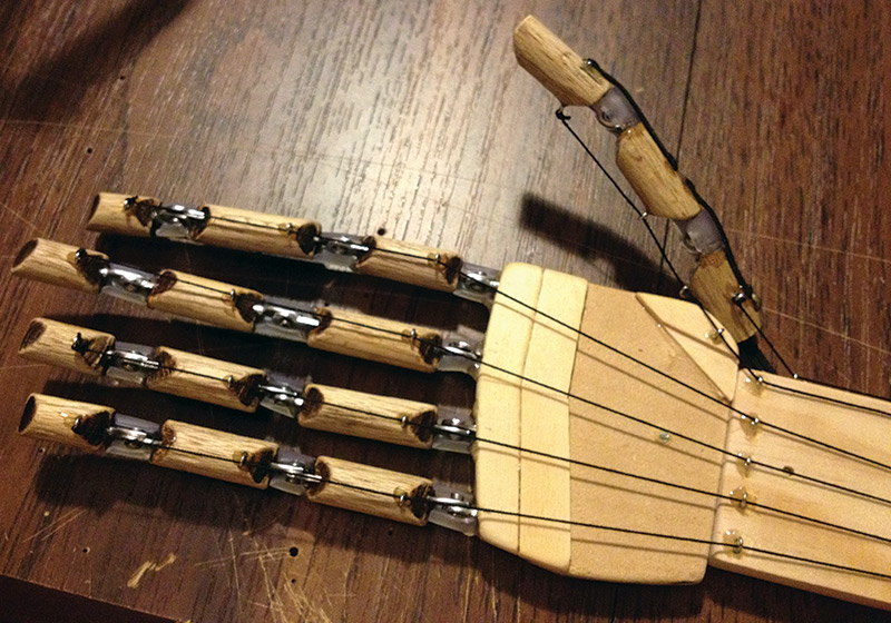
FIGURE 13. Tendons all threaded and ready. The anchor point to swivel the thumb assembly can be seen at the bottom of the thumb.
The control board PCB is quite easy, as all you need to do is solder six sets of three header pins (break-away header pins) to plug the servos into, four momentary pushbuttons, four 10K ohm pull-up resistors for the buttons, and wiring to go to the Arduino (Figure 14).
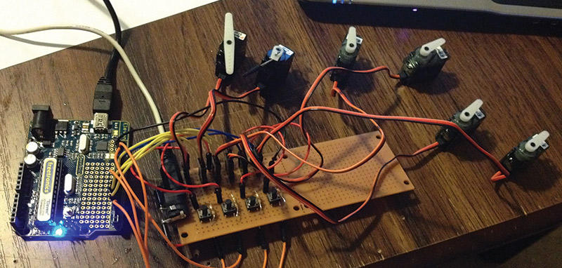
FIGURE 14. Testing the control board PCB connected to an Arduino Uno, with all six servos.
Finally, pick a DC jack that fits a 5V power supply. In my case, I had an old Canon camera USB battery charger sitting in a box. I won’t go into the detail of soldering the control board, but the supplied Fritzing diagram will guide you on the layout (Figure 15).
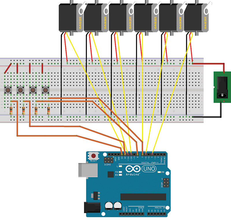
FIGURE 15. Control board layout using Fritzing.
With assembly and soldering complete, I sat back and thought, cool! Now, let’s get this moving!
Programming the Arduino and Testing
Once I built the mechanics and soldered the control board PCB, it was time to do the coding. I used four pushbuttons on the control board so I could activate the functions I wanted. Each button required a 10K ohm pull-up resistor between the button legs (both positive and ground connections) and jumper wires going from each button to four available digital pins on the Arduino.
I had thought about using flex sensors in a separate glove arrangement instead of buttons to control the functions, but that would have required more code and putting together a suitable glove. I still liked this idea, though. So, the four pushbuttons would trigger four basic functions, each containing a set of actions:
• Button A = Open and close all fingers and thumb together
- Set slow speed
- Close the four fingers at the same time
- Swivel thumb up and close it
- Open thumb and swivel down
- Open the four fingers at the same time
• Button B = Move each finger then thumb independently, slow then fast
- Set slow speed
- Close and open finger one
- Close and open finger two
- Close and open finger three
- Close and open finger four
- Swivel thumb up, close and open, swivel down
- Set fast speed
- Close and open finger one
- Close and open finger two
- Close and open finger three
- Close and open finger four
- Swivel thumb up, close and open, swivel down
• Button C = Finger and thumb pinch — “precision” grip of something
- Set slow speed
- Swivel thumb up
- Close finger one and thumb at the same time
- Open finger one and thumb at the same time
- Swivel thumb down
• Button D = Close and open fingers and thumb alternately and fast
- Set fast speed
- Close and open finger one and finger four at the same time
- Close and open finger two and finger three at the same time
- Close and open finger one and finger three at the same time
- Close and open finger two and finger four at the same time
After attaching the tendon string to the first finger and threading it through all the eyelets, I would pull the other end of the string — which closed the finger — across a piece of paper and would mark the position of the end of the string. Then, after releasing the string with the finger returning to open, again I marked the end of the string on the paper.
This allowed me to measure the distance the string travelled, and therefore how far the servo needed to travel to open and close each finger.
This measurement would be used to fine-tune the servo travel angle in the code for each finger.
Using the example Arduino ‘sweep’ sketch, I connected a single servo to the Arduino, secured it to the table alongside the above measurements, and ran the program.
Watching the tip of the servo horn as it moved back and forth, I could clearly see that the travel angle I needed was a full 180 degree sweep. However, the length of the servo horn was too short as it didn’t travel the full horizontal distance needed. So, I made a small wood extension for each servo horn and made sure the distance they travelled once attached to the servo matched the horizontal measurements (Figure 16)
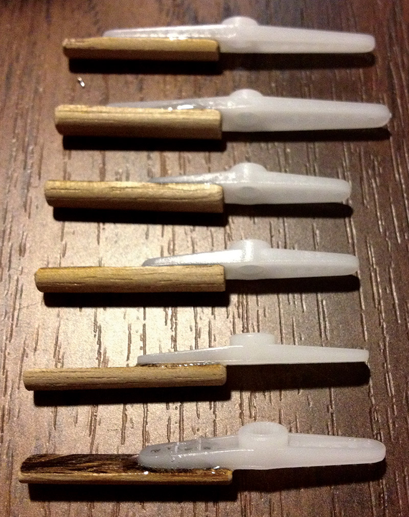
FIGURE 16. Servo horn extensions — used to increase the servo travel angle horizontal distance — so fingers could be fully closed and opened.
With those key measurements done, it was time to write some code. I started with the basics of attaching the buttons to digital pins:
- buttonPinA = digital pin 13
- buttonPinB = digital pin 12
- buttonPinC = digital pin 7
- buttonPinD = digital pin 2
The servos were then connected to the Arduino as follows:
- myservo1.attach(11); Pinky finger attached to PWM pin 11
- myservo2.attach(10); Ring finger attached to PWM pin 10
- myservo3.attach(9); Middle finger attached to PWM pin 9
- myservo4.attach(6); Pointer finger attached to PWM pin 6
- myservo5.attach(5); Thumb (swivel up/down) attached to PWM pin 5
- myservo6.attach(3); Thumb (close/open) attached to PWM pin 3
Each button press would be linked to a statement in the code: if (digital Read) (button Pin A) == HIGH). Or, if button A was pressed, then execute a for loop containing a group of myservo1.write(n) statements to move the servos and thus the fingers.
Again, looking at the example ‘sweep’ sketch, the for loop contains the variable pos (position). It is this one variable that is used to assess the condition to stay in or exit the loop, as well as incrementing/decrementing the counter. More importantly, this variable represents the servo position value for the myservo1.write(n) statement, where n is replaced with pos. As the loop runs, the pos value (which begins at 0) is incremented, and thus the position of the servo is changed one degree at a time by using the myservo1.write(pos) statement.
So, basically the code was repeated until a condition was met, then stopped. In this case, the condition was if the value of pos is equal to the maximum travel angle position value — which was 180 — then stop.
All the above code represented moving the finger from the open to the close position. To move it back to open was easy — it was just a matter of adding a second loop, but starting with a value of 180 and counting in reverse (decrementing the counter). This second loop followed the first, resulting in the full close and open movement.
I watched how fast the servo rotated based on the code, and how by including the time delay function delay() after each individual or group of write() position movements, the rotation speed could be increased or decreased, and thus the speed of the fingers closing and opening could be changed. For example, delay(5) would cause the program to pause five milliseconds before continuing to the next write() position statement.
I attached the string to the servo horn and executed the code. The results were in: It worked great as the first finger closed and opened smoothly, and as planned. Woo hoo, I gave myself a high five!
After this success, it was a matter of replicating the code and adjusting it slightly for each finger until they were all done. Be sure to test each finger independently, and when satisfied you can combine the code so multiple fingers move at once. The thumb was a little more challenging, so I chose a basic movement model:
- Swiveling the whole thumb up
- Closing the thumb
- Opening it, then
- Swiveling back down to lay flat with the palm
It took some time to get both servos working together as I wanted, but by breaking the two movements into separate actions, eventually the final movement was smooth and integrated.
The coding was complete, testing had identified some fine-tuning that was needed, and — best of all — I had a cool working robot hand with four functions. I was quite happy and knew that if I could accomplish this, then I could do so much more using the Arduino, great little micro servos, and a lot of bits and pieces!
Behold, the Little $300 Wooden Robot Hand!
Having succeeded with the project, I wanted to show the world! I created a few basic videos of it in action, merged the results, and uploaded it to my YouTube channel.
In demonstrations, people are quite taken with it and their questions and delight make the whole experience even better. I enjoy explaining how I built it and how it functions, even inspiring friends at work to go out and experiment with an Arduino and the work-horses of mechatronics — the servo. Overall, I thoroughly enjoyed my foray into mechatronics. Although I haven’t fired the hand up in a while and have since repurposed the servos, it still has a prime position on my workshop shelf. What’s really great is all of the components and parts came to under $300!
Challenges and Obstacles
Given the simple nature of the components, there really weren’t many major problems or challenges.
The first problem I encountered was the servos I’d harvested from an old four-channel RC helicopter. They were basic unbranded micro servos, and although they’re not bad to begin with — especially considering the low cost involved — they’re designed to be harnessed to the helicopter frame, so the servo housing base plate is not secured to the rest of the housing with four screws like you would usually see.
This meant the plate kept popping off, grease inside was leaking out, and they really weren’t secure like regular servos. Initially, I put a rubber band around the whole housing which stopped the insides from popping out. However, despite this, in the end they just weren’t up to the task — a few stripped gears and a failed motor appearing as time went by.
As I have been flying e-Flite Blade RC helicopters for several years, I knew their micro servos were reliable, strong, and relatively cheap. So, I went ahead and bought six servos to replace the others.
The next hurdle was the Arduino. My coding experience with C and VB was many years ago and totally removed from microcontrollers. The ultimate end result of this project was multiple servos doing multiple things at the press of a single button (four buttons/functions in total), so it was a steep learning curve.
However, after discovering the online community, downloading a few sample sketches, and blowing away the coding cobwebs in my head, I wrote my first basic sketch to move a servo using PWM (pulse width modulation).
It was really easy, and the code is simple to understand. So, all in all, the challenges were fun, relatively easy to work through, and not daunting “can’t sleep at night” problems. The beauty of the Arduino is the massive community online with help just a search away, along with great write-ups on various websites such as Arduino.cc, Adafruit, and SparkFun. Plus, there’s the articles available in issues of SERVO and also Nuts & Volts (www.nutsvolts.com).
Newer More Challenging Versions
Fast forward and I built an all metal version of a similar hand. This time, I used spring wall anchors/toggles for knuckles and 10 pound braided fishing line for tendons. Once again, I used parts that could be easily found at a hardware shop along with the same Arduino Uno and e-Flite micro servos.
The metallic hand looks a bit cooler — in a Terminator way — like an exoskeleton. It has full wrist rotation and wrist flexion/extension movement, along with finger splaying/adduction (although I never finished that function).
I'm looking at working on a version 3, made mostly of 3D printed parts, and using linear actuators I'll design myself. It should be much more efficient, precise, and complian. The pipe dream is to make an inexpensive, capable, and modular mechatronics kit for kids and hobbyists.
If that works out, and as the design improves, my ultimate vision is to make affordable, easily customized prosthetics for lower limb amputees. SV
Advice/Tips
- Get a fresh supply of epoxy and super glue.
- Use strong string/thread for the tendons.
- Make sure the servos are mounted tight to the forearm.
- Let the epoxy cure.
- Test the code and servo on their own BEFORE connecting them to a finger.
- Enjoy yourself and learn about mechatronics.
- Let the creative juices flow.
Parts List
- Piece of 10 mm x 50 mm x 400 mm pine (forearm)
- Piece of 10 mm x 60 mm x 70 mm MDF (palm)
- 1 m long piece of 10 mm diameter wooden dowel
- Right angle plastic bracket (to mount servos to forearm)
- Paddle pop sticks (not required)
- Silicone tubing x 200 mm
- Black elastic
- Strong thread/string
- Metal eyelets
- Tea infusers
- Arduino Uno (or similar)
- Jumper wires
- Pushbuttons
- Resistors (10K ohm)
- DC jack
- Breakaway header pins
- Servos x 6 (I used 7.6 gram DS76 digital sub-micro servos)
Tool List
- Drill and drill bits
- Alligator clips
- Small rubber bands
- Epoxy
- Super Glue™
- Blu Tack
- Pliers
- Dremel or hack saw
- Soldering iron and solder
- Arduino IDE (v1.0.4)
Resources
www.youtube.com/watch?v=t52edTD9RA0
www.youtube.com/user/petethedreamer/videos
Arduino.cc; Adafruit.com; Sparkfun.com
https://www.e-fliterc.com
Article Comments